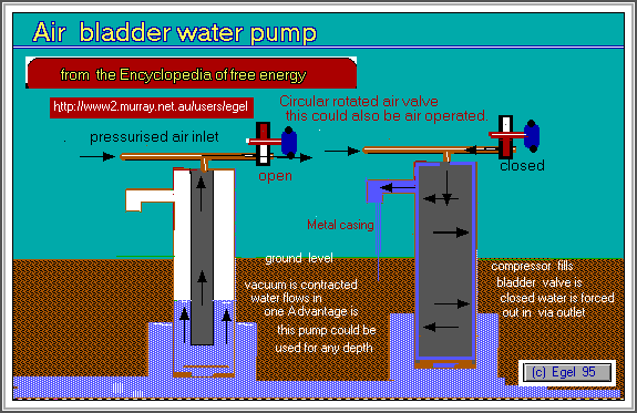


A simple valve in bottom of pvc piping, this need not be anything special.
A simple one could be a light piece of rubber cut in a circular shape and placed over an end cap with a reasonable size hole drilled in it.It could also be connected to bottom of badder and bottom of the end cap tubing, with a hinge so that it could be operated when the bladder expands and contracts.
A water outlet on the side of the PVC tubing and a reliable air pressure source. An air pipe of tubing made in a T shape this will be the means the air is supplied to rubber bladder.
The pipe section of tubing entering bladder would need to be of a smaller diameter that the rest . At the opposite end to air inlet a means would be needed to open and close air pressure supply.
This could be a simple rotary valve or electrical device operating by the unit itself. A much simpler solution could just be an air tap operated by hand when water is needed.
Experimental Version
A experimental version could be made by using a smaller diameter Pvc tubing a t piece inserted in middle to make an outlet and a bicycle tube. A bottom valve made as described previously.
Place the complete bicycle tube bent in half in the pvc piping so that air valve is at the top. Place the pipe pump in a water source and then using a bicycle hand pump inflate tube. You will need to find a way to deflate the tube. This will not need to be a problem if you use a continuous source of air and the t bar air inlet as previously described. If you are using a continuous source of air pressure such as an air compressor remove the rubber in valve stem of inner tube so that air can flow in both directions without hinderance.
Theory of Operation
Air at beginning is directed into rubber bladder by turning the air outlet tap to off position. The increasing pressure of bladder causes the bottom valve to be forced shut. The bladder continues to inflate and water is forced up the pipe until it exits out the outlet. When all water is expired. The air outlet tap is opened so that air escapes and pressure in bladder is decreased and the Bernouli effect takes place to cause the badder to be compress. This causes the bottom valve to be opened allowing more water to enter tube. The compressing of the bladder may also assist in drawing water into the piping if the water outlet is not too large or has a non return valve in it [ although it is not necessary to this design.]
I believe this device should work to any depth if air pressure can be maintained greater than water pressure depth.

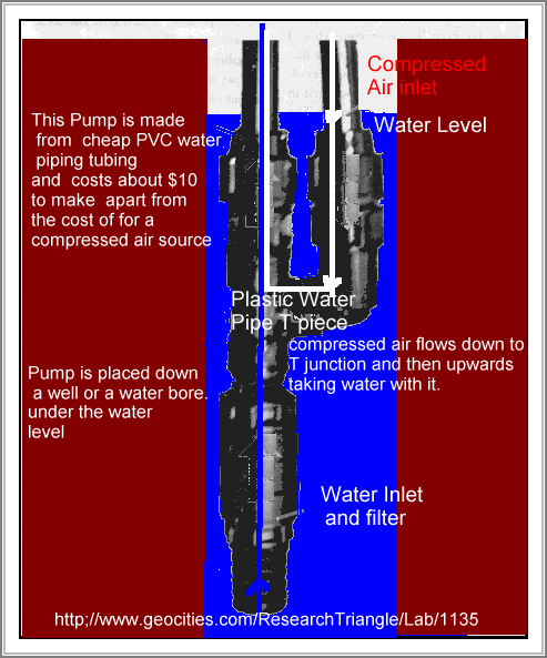
The design is simplicy itself and has no moving parts but relying on what is called the air lift effect and can be put together in few minutes.. The pump used Piping than can be obtained from irrigation plastic pipe supplier and should cost no more than about ten dollars to construct for your self.
A compressed air supplied is also required and that can be used from an electrical operated power supply or petrol operated one and for some of you with a windmill it may also be use it generate a compressed air source with some modifications( outside scope of this article ). You will also need to experiement with compressed air pressure to get the unit to function porperly too little pressure, or too much will cause the unit to non function.
The pump consists of a polypipe plastic T piece and some simple poly pipe pieces and construction should prove not to be difficult.
Below attached is a length of poly pipe a meter in length of so, to which then is attached a filter or screen to prevent vegetable or sand or rubbish being drawn into the pump inlet.
A simple strainer could be a piece of pipe block off with small holes drilled in the side of it to allow the water access to the pump inlet section.
To the middle part of the t piece piping is where you attrach your compressed air inlet supply.
The top part is where the water carried by the air will be pushed upwards and outwards to your desired collection area.
The Pump is lowered in a water soure well or bore, so that all the T section is totally immersed in water and the pipe inlet is postioned above the bottom of well so that it does not enable foriegn material such as dirt stones etc to be drawn into it (a metre or so from the bottom ).
When the unit is placed into water supply ,so both the water pipe and the air line will fill with liquid water.
With the air pressure is turned on it will force the water down the air line and up the water outlet.
The air pressure will drop suddenly and water from the inlet will rush into unit to recompress the air in the water pipe.
A colummn of air is trapped in the feed pipe and the next supply of water added. This weight of water forces a air tight seal and also draws into it, because of reduced air pressure it will draw more water in the air inlet pipe section and with the cycle continuing to operate as long as air supply is allowed to continue.
This pump should be able to give you approx 10 litres per minute.

