Radioactive Battery 111604
Part one
Part two / Part three / Part four / Part five appendix
by Richard R. Annis 6th August 1952
Approved by I.O Myers Chief Nucleonics Branch
Copy no 55 M.1456
SC Proj No 212ADept of the Army Project No 3-12-80-021
Evans Signal Laboratory `
Delmar New Jersey
TABLE OF CONTENTS
1 Foreword
2 Summary
3.Discussion
4.Conclusions
5.Acknowledgement
6.References
APPENDIX:
Fig. 2. Volts Potential in Air Compared to EMF Series.
Fig. 5. Change in Contact Potential with Temperature
Fig.6.Al. Pt. Cell
Fig.8.Al. Pt, Cell (Experimental Arrangement)
Fig.9.Output Current vs Dosage Rate for Al. Pt Cell
Fig.10.Output Current vs Plate Separation Distance with Constant
Radiation
Fig.11.Greinacher's Curve of Output Voltage vs Plate Separation
Distance
Fig.12.Output Current vs Plate Area
Fig.13.Al - Cu Cell
Fig.15..Experimental Arrangement for Tests Conducted Using Different
Filling Gases
Fig.16. Output Current vs Dosage Rate for Nitrogen Air with
..Different Plate Separation Distances
Fig.17. Output Current vs Dosage Rate for Argon. Nitrogen & Air with Different Plate Separation Distances
Fig.18. 97 Cell Al - Cu Plate Battery
Fig. 20. 212 Cell Battery
Technical Memorandum
Radio Active Battery
- Foreward
This report is the result of an experimental investigation of contact potential leading to the development of a radioactive battery. A theoretical discussion of contact potential is outlined. Various methods of measuring contact potential are given, and a detailed discussion of the method used by the author is discussed. The factors to he considered in contact potential are discussed together with experimental results obtained in the laboratory. The test results obtained on various cells built are given. A detailed discussion of the design factors to he considered in building a radioactive battery are discussed completely. The results obtained on a radioactive battery constructed and tested in the laboratory are given. The advantages and disadvantages of a radioactive battery are weighed.
2 SUMMARY:
This paper has given a detailed explanation of contact potential.
Factors affecting contact potential have been mentioned.
Various methods of measuring contact potential have been outlined.The results of measurements made of contact potential have been given together with comparisons of other experimenters. The results of making cells using two dissimilar metals and X-radiation have beengiven.
Theoretical and experimental results obtained by making a
from the cells are shown. The design and test results of a radioactive battery resulting from this experimental work is explained in detail.
3.DISCUSSION:
THEORY OF CONTACT POTENTIAL
(1). DEFINITION & HISTORY
(a)Contact potentially is the potential that exists between two dissimilar metals in contact with each other.
This phenomenon exists because of the difference in work functions of the two metals. Electrons escape from the surface of all metals. Since the work function of a metal is defined as the amount of work required to free an electron. one can see that if two metals are in contact which have different work functions, there will be a difference-in potential between the two metal.
(B)Contact potential occasionally referred to as Volta effect was discovered and measured by Volta in 1797, Well known figures such as C. E. Maxwell, 1. Ostwald.0.Lodge and others thought that the true contact potential between pure metals was negligible. They felt that the observed magnitudes
were due to impurities such as absorbed gas layers or thin layers of electrolytes adhering to the metallic surfaces
It is only in relatively recent times that a decisive state has been reached.
Notable contributions toward this end were the experiments of Coehn(2)
Perucca (3) who revealed that reproducible measurements could he made, and the theoretical treatments of Sommerfeld(4) and Eckart(5)'who
predicted the existence of contact potential differences of the observed order of magnitude from the physical considerations.
THEORETICAL DISCUSSION
The theory of electrical (6) conductivity leads to the conclusion independently of experimental evidence that a potential difference ,
should exist between the interiors of two metals in contact even when
their temperatures are equal. In the Equilibrium State this is represented by the equation

Where S is the Gibbsian thermodynamic potential of the electrons. designated as the Fermi energy at temperature T. and e is the
electronic charge.
The quantity (V2 - VI) cannot be measured, however, owing to the fact
that its magnitude depends upon the zero-point energies in the
two metals. For free electrons, these energies may he regarded as
equal to zero. In this case S1 and S2 represent equally kinetic energies, and the internal field shifts the energy zero by an


Although the internal field in not measurable the-contact potential
that is, the difference in potential between two points just outside
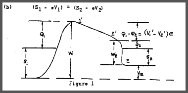
each metal, is independent of the zero point energies, and hence measurable. The situation is indicated in Figure. 1.
Here - W1 and -W2 are the potential energies of an electron in the specified metal relative to a vacuum. whereas Ql and Q2 represent the respective work functions. The potential difference between points 1' and 2', or the contact-potential, is given by:

e e
If the work function is given in electron volts. the contact potential in expressed as follows:
(d)C.P. = W1 - W2
C.P. = Contact Potential In Volts
W1' & W2'= Work function in electron volts
3)COMPARISON OF VOLTA SERIES TO EMF' SERIES
The order of metals arranged. according to work function values from the alkali metals with very low work function to platinum with a very high work function parallel to some extent the EMF series. Fig. 2 shows the Volta (7) potentials for metals abraded in air compared with the standard potentials of the usual EMF series.
b.METHODS USED FOR MEASURING CONTACT POTENTIAL:
There have been a number of methods devised for measuring contact
potential. The most common types will he outlined.
1)IONIZATI0N METHOD
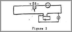
This method was first used by Kelvin(8). Essentially this scheme consists' of ionising the medium between two metals. Using a galvanometer. vibrating reed electrometer or come other indicating, device connected in series with the two metal plates. and a variable voltage for nulling the detecting device. When the bucking voltage equals the contact potential of the two metals, the current in the circuit will be zero. This was the scheme used for the work on the radioactive battery to be mentioned later.

CONDENSER, METHOD
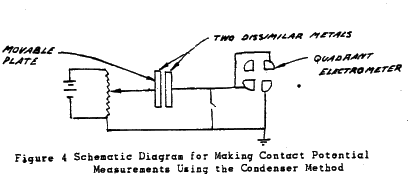
This method was originally used by Kohlrausch (9) This system consists of making an air condenser of the two metals. using a quadrant electrometer to indicate the charge and nulling voltage.
The main problem associate with the condenser method is the necessity of moving one plate to obtain a voltage amplification. By separating the plate distance, a decrease in capacitance results which results in an increase in voltage.
Zisman(l0) improved on the original condenser method. He vibrated one of the plates by blowing air on a steel piano wire.
Thus an A.C.voltage outputwas obtained. This signal was applied to an audio amplifier andheard. A nulling voltage was adjusted until no signal was heardand thus the contact potential was obtained.
In later experimentsthe plate has been vibrated electrically. The condenser method is the only scheme that measures contact potential directly. It has the advantage of being able to make measurements in a vacuum. Its most unfavourable aspect is the necessity of having to move one electrode.

Figure 4 Schematic Diagram for Making Contact Potential Measurements Using the Condenser Method
Other methods have been used for measuring contact potential such as.
(a)Curve Displacement Method
(h)Saturation Current Method
(c)Diode Method
(d) Triode Method
In each of the above schemes a special tube is made with the two metals incorporated whose contact potential is to be measured. Theme methods do not seem to he suitable for laboratory research work on a radioactive battery, where a number of different metals will have to he investigated.
Next Page


