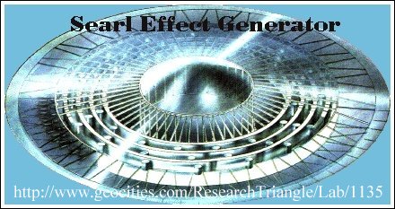

The Searl Effect Generator (SEG) consists of 3 stationary rings with movable rollers. Both the ring and the rollers are made out of 4 distinct materials, making it magnetic diodes, meaning that electrons can enter only in the middle of the roller and exit on the sides.
Best used materials are from outside to inside : Aluminum (paramagnet), iron, nylon 66 (positively charged to attract electrons), neodymium (for use as a magnetic mirror to attract electrons). Basically the whole unit is a magnetic diode, electrons can only enter in the middle of the machine and get accelerated outward..
Normally you magnetize materials with DC power to get 2 poles, however , you can also make a 3 pole magnet or a 20 pole one.
Now these rollers and rings have a sinus form pole (this is accomplished by magnetising a roller with AC),
If you have the rings and rollers magnetized the same way (same "comparable" AC frequency), and put them 90 degrees out of phase, (basically a sine wave pole on the roller and a cosine wave pole on the ring and put them together in this unstable condition) they will move.
If you draw this out you see that it constantly attracts or constantly repels.
The roller would not spin on its own axis to get to equilibrium, this is because the forward push and the rotation are balanced out to stay at 90 degrees off phase..
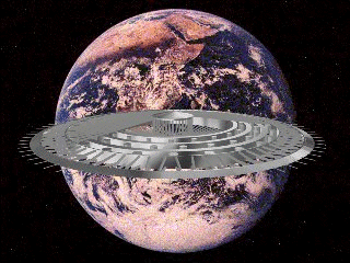
Thanks to aluminum, the rollers do not shoot away from the ring.
This is because a changing magnetic field which is the case with the rollers going around the ring, will effect aluminum (paramagnetic property) so that is sticks to the ring but does not touch it.
Searl showed the properties of one of these magnetic diodes by putting a wire in the middle of the roller and one on the outside and brought them together in a oscilloscope.
It showed on the oscilloscope that there was a current moving in them and not dissipating in intensity.
Well, what happens to the whole machine. The attraction of electrons out of the surrounding air will ionize the air surrounding the machine, making the machine glow.
These electrons are "sucked" inside the SEG and are accelerated outward. You can catch these electrons on the outside with an ordinary metal brush, and you can create a propulsion system just by putting these electrons inside a CRT and aiming it in one direction.
Supposedly you can use the disk as transportation, but it has never brought me anywhere yet. Some interesting phenomena's are "anti-gravity" and its own space time inside.
Hereby I mean a constant gravity of 4.4m/s^2, no matter what the acceleration of the unit is.
You cannot detect the machine by radar, because it will suck up that radiation as well. To control it, you can use a regular radio transmitter with a frequency of one of the harmonics used to magnetize the system, this will slow down or speed up the rollers.
The limit to the speed of this disk is unknown but most likely far beyond the speed of light, (In contradiction with most theories, but keep in mind that it supposedly has its own space time inside. Later on I will brainstorm you with some of my ideas on space time which
I really like to get some feedback from you, if you disagree from it or
not).
For the purpose of flight, the SEG is more than
perfect. Inside the disc you do not feel acceleration, turbulence
etc., and it is supposedly quite comfortable
(There is no record of any live form which has gone aboard, but it does have records on meters which have gone with it) UFO's are an entire different subject, but I like to point out that this machine flew since 1946.
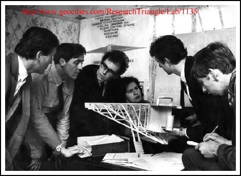
Right now prof. Searl is working on a big model in England, and in Germany and the States some members of the D.I.S.C. are working on a smaller version.
The rings and rollers are almost finished and you can see the developments on SEARL's HOME PAGE (link below).
There is a thorough knowledge required on the law of the squares to built the SEG (ancient Chinese called these the magic squares.
Magick studies are using them, I refer to MASTER THERION studies, where the number 666 is found, which in religion has the meaning of the number of the beast.
Searl used them to basically construct the SEG.)
These squares are based on a very simple law. You cannot have matter in the same time and in the same space, but you can have matter in different spaces in the same time or same space in different times.
For example, you need to know how much aluminum (paramagnet) you need to cancel out the centrifugal (pseudo)force etc.
Design and Manufacturing Procedure
The objective of this report is to reconstruct the experimental work carried out between 1946 and 1956 by John R. R. Searl that concerns the geometry, materials used, and the manufacturing process of the Searl-Effect Generator (SEG).
The information given here is based on private communi- cation between the author and Searl and should be considered preliminary as further research and development may give reason to alter and/or update the content.
The Gyro-Cell
The SEG consists of a basic drive unit called the Gyro- Cell (GC) and,depending on the application, is either fitted with coils for generation of electricity or with a shaft for transfer of mechanical power. The GC can also be used as a high voltage source. Another and important quality of the GC is its ability to levitate.
The GC can be considered as an electric motor entirely consisting of permanent magnets in the shape of cylindrical bars and annular rings.
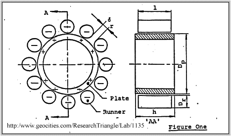
Fig. 1 shows the basic GC in its simplest form, consisting of one stationary annular ring-shaped magnet, called the plate, and a number of moving cylinder-shaped rods called runners.
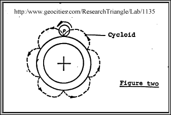
During operation each runner Is spinning about Its axis and is simultaneously orbiting the plate in such a manner that a fixed point p on the curved, runner surface traces out a whole nwrber of cycloids during one revolution round the plate, as shown by the dotted lines In fig. 2.
Measurements have revealed that an electric potential difference is produced In the radial direction between plate and runners; the plate being positively charged and the runners negatively charged, as shown In fig. 1.
In principle, no mechanical constraints are needed to keep the GC together since the runners are electromagnetically coupledto the plate. However. used as a torque producing device shaft and casing must be fitted to transfer the power produced. Furthermore, in applications where the generator is mounted inside a framework, the runners should be made shorter than the height of the plate to prevent the runners from catching the frame or other parts.
When In operation, gaps are created by electromagnetic interaction and centrifugal forces preventing mechanical and galvanic contact between plate and runners and thereby reducing the friction to negligible values.
The experiments showed that the power output increases as the number of runners increase and to achieve smooth and even operation the ratio between external plate diameter DP and runner diameter Dr should be a positive Integer greater than or equal to 12. Thus
D
p = N > 12 (N 12, 13, 14....)
r
The experiments also indicated that the gaps 'r between adjacent runners should be one runner diameter Dr as shown In fig. 1.
More complex Gyro-Cells can be formed by adding further plates and runners to the basic unit Fig 3 illustrates a 3 plate GC consisting of three sections,A, B and C. Each section consists of one plate, with corresponding runners.
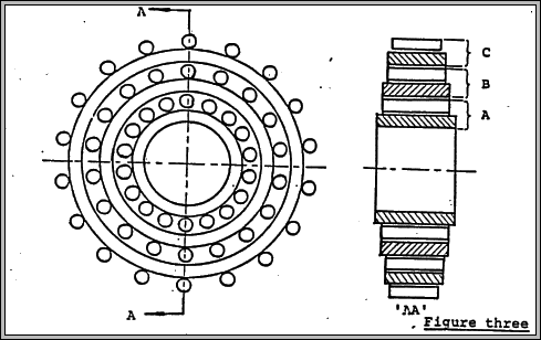
The experiments showed that for stable and smooth operation all sections should be of equal weight. Thus
WA = WB = WC
where
WA weight of section A, WB weight of section B, and WC weight of section C.
The Magnetic Field Configuration
Due to a combined DC and AC magnetising process, each magnet acquires a specific magnetic pole pattern recorded on two tracks consisting of a number of individual north-poles and south-poles as illustrated in fig. 4.
Magnetic measurements have revealed that the poles are approximately one millimetre across and evenly. spaced. it was also found that the pole density 6 - defined as the total number of pole N per track'divided by the circumference nD must be a constant factor specific for a particular generator.
Thus
N Nr
P constant
pi D n Dr
Some additional other points to ponder
The estimated porter output of the generator is some modest 10^14 or 10^15 watts which puts the figure too high for a solar source.
Inertia loss.
Above threshold potential, which must be some 10^13volts, the generator and attached parts become inertia free. This of course jars with accepted concepts of inertia in mass.
Drive.
By altering the distribution of potential on the surface of the craft, it is possible to propel it. The preferred direction of travel at ultra high speeds is away from the planet, the plane of the generator being at 90 degrees to-the Gravity field.
Vhen in horizontal flight, the craft takes up an angle to the Gra- vity field suggestive of the balance between like vector fields. The generator may produce a gravity-type field of its own.
Ionization of the air.
This is a simple electrostatic effort. It gives rise to a translucent glow surrounding the craft and glowing trails.The intensity of the field is such that it is capable of excluding the ionized air creating a near vacuum around the craft.
Permanent electric polarity.
Searl noticed that,after working near the craft or generators he had a "cobweb sensation on the skin. His clothes clung to him and also the bed linen. This was accompanied by occasional crackling and lasted some hours.
This effect could be attributed to a permanent polarity of dialectric material, in in this case, the Material being body tissue. Little work has boon done on permanent dielectrics, but reference may be found in the records of the Physico-mathematical Society Qf Japan, 1920.
The work was carried out by Prof. Eguchi Tokyo.
An American company is at the moment producing permanent electret material for electrostatic loud speakers.
matter snatch during acceleration.
This occurs when the craft is on the ground and the drive is suddenly stitched on. The rising craft takes up a lump of the Ground with it, leaving the well known hole in the ground.
I believe it should be nylon 6:6
JOHN R.R. Searl mentions it in construction of his Levitation disk on this page.
I found this is and below is from a high school chemistry book detailing how it is made.
Lets Experiment Making a condensation polymer nylon 6:6
Aim to make nylon 6:6
Apparatus
100cm^3 breaker
10cm^3 of 5% solution of 1,6- diaminohexine
10cm^3 of 5% solution of adipyl chloride in hexane
glass rod or pair of tweezers (optional)
Method
1 Place 10cm^3 of the adipylchloride solution in the breaker
Add die to the solution (if desired)
2 Carefully add the 1,6 diaminohexine solution so that two solution don't mix
3 A small amount of solid will form at the interface of the two liquids.
Using a glass rod or a pair of tweezers pull out a little of this solid and carefully wind the thread around the rod or tweezer.
The thread will go on forming until the solution is used up.
Nylon forms at the interface between the two organic liquids in the breaker.
Take a look at his page for additional information of R.R. Searl Searl-page