
Please note:
Some people have reported to me difficulties in getting this device to work.
You need to have some good clean fresh water for this thing to work,
I tried normal rainwater stored in plastic tank here and it did not work either.
I charged this water up using a vande graf generator and the dripper then worked as described although not well.
I think water from a reservour supply may not work as well as it sits in a storage area and in metal pipes and with this subjected to chlorine and flouride and with the ambient heat to keep it drinkable although nature lovers would consider this water dead.
I may be wrong but if you can get some pure clean mountain or running spring water you may be more successful.
if the water is chilled to 4 degree celsius this may also help as water seems to lose something when heated
by the hot sun when out in the open
The best water it seem to be something stored in darkness and kept chilled if you are to believe followers of Viktor Schauberger
If you used poly pipe this stuff when it gets damp will conduct electricty away from the cans and I suggest you varnish all the plastic of it using a natural vanish not the petrol chemical version or use a better supporting material.
Wood restorers or hardware suppliers may be the source to try.
The water also has to drip and not be a continous stream but a drip by drip operation.
If the air is moist around the device such as high humidity or rain in the air ,it will not work also as the charge will not be allowed to build up due to the water conducting the charge into the surrounding enviroment.
It should however work great if you have a thunderstorm , A good dry environment is what you are seeking.
if others out there have suggestions that make this device work I would welcome your input here
Geoff
From an associate of the original inventor of the Kelvin Can experimental device.
Subject: Re: Kelvin Generator
Apologies for not replying earlier, I have been away.
We use ordinary tap water, which in this area is quite 'hard', with high
mineral content. We tried using distilled water but it wouldn't work
properly.
Please note the webmaster has found that rainwater stored in Plastic storage tank for a long period of time does not work as well.
We also found that if you lightly greased the grey plastic
pipework with silicon grease or similar, the effect was a much inproved
spark gap & faster spark repetition.
This seems to prevent water build
up on the pipework which we found affected charge build up.
Under no circumstances get any kind of detergent such as washing up
liquid anywhere near it, as this kills the charge build up immediately!
Hope this helps. Please let us know how you & everyone else get on.
Regards, Ian Helliwell.
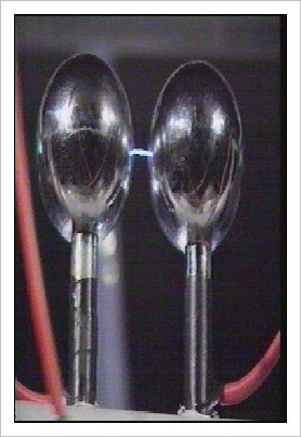
In the late 19 th century and early 20 th century there was performed a nearly forgotten experiment that generated static electricity. by lord Kelvin as shown in the photograph below.
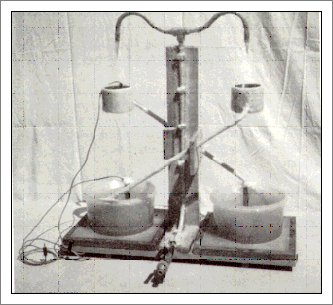
These following examples are a modified form that will give better results.
The frame work is made of PVC tubing that holds 4 x 1.5kg empty coffee tin cans or anything made of metal.
This is a diagram of the basic setup of the unit.
Notice the criss cross wiring of the cans this is same for all units shown.
The red conductive lead are crossed on the front of the unit.and an electrical conductive pathway is made between the two cans.
The black leads are connected on the back of the unit in an opposite manner.
The black lead and the red leads then are joined to the seperate sides of a spark gap.
A small pump recycles water from the bottom to the two sprinkers above the two top cans and then
sprayed into the top cans and then drips by means of gravity into the cans below.
The water then drips into a collection tray below and is then again pumped up agaian.
The water carries electrons from one can to another and acts as a voltage doubling circuit building up voltage levels until a discharge occurs at the spark gap.
The top of the upper two tins will contain small plastic micro garden sprinklers popularly used and very cheap.
Both of the bottoms of the uppermost cans have about a two inch centre hole to allow water to drip into can below..
The two bottom cans have there tops completely removed and small holes punched in the bottom of each can to allow water to drip into a common collection tray.
Water is pumped through the plastic tube from the collection tray via a small car windscreen water pump and sent to the two sprinklers mounted in the lids and then the water drips through the can until it reaches the collection tray.
distance between top and bottom can should be such that water drips and is not a continuous flow.
Wire leads are connected to di-anglar cans and then to a spark gap terminal
When water is flowing a spark should be generated every twenty seconds experimentation will be needed to adjust the spark gap for better results.
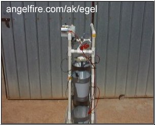
Below are several photographs of a version using 4 buckets connected in a criss cross way as described and shown on A British TV education program.
This Generator produced from household drainpipes etc as pictured above was designed & built by Mr M Hill of the Physics Department, University of York, England. The Generator is alive & well & continuing to give pleasure & amazement to the general public.
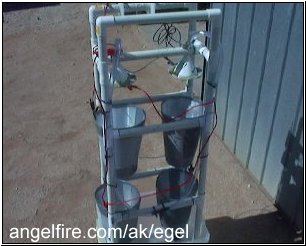
A view from the bottom looking up wards
You are unable to see it but there are holes placed in the bottom buckets.
A view looking from the front with water flowing and pumped through the unit from the bottom collecting surface and returned to funnels placed above the buckets.
The water delivery from funnels at top of unit
How charges are distribruted on the four buckets that are cross connected.
In this unit a charge is discharged at every 20 seconds.
Greater results may be be obtained if you add more crossover stages.
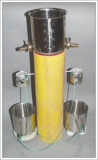
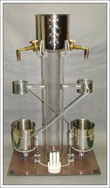
Below the author's attempts to make a similar device as to the one shown above.
I believe my latest version is much better than my first unit.
side view of web authors unit
back view of web authors unit
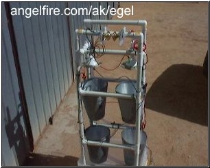
front view of author's unit notice the brass door knobs used as a spark gap.
The unit is made using PVC irrigation piping 3/4" in diameter
Construction is made using plastic pipe lengths cut to the same length and with four angle joiners and 12-18 T connectors depending on your construction choice.
The drums were made from some offset used aluminium sheeting cut to size as I found it easier to bend than other metal I had at hand.
I think any available metal should be okay to use.
The angle to cut the metal sheeting is important and you should end up have the shape of a bucket when the two ends are joined together.
I cut up a used cardboard chip cup or you can also use a take away drink container cut down one side to get the right angle to the metal you desired to use. although you will need to size up the cut out to make larger containers.
I traced the shape out on some cardboard and gradually increased the size until I finally got the size I wanted and used it as a template to draw on the metal I needed to cut.
I used gaffer tape when joining the two ends of the flat metal cut so as to form the bucket shape.
Please note,If you use one piece it will not form a bucket shape.
But I have found if you put three pieces together one inside the other the shape naturally resulting will be the correct bucket shape.
So you will need to cut twelve pieces of metal out to make the four cups or buckets as shown in photos above.
The bucket is then put together with some plastic gaffer tape and when a new insert is added I put some contact glue on the metal to help make it more rigid and glue the sperate pieces together.
When I put the bucket shape together I inserted some metal fly door screening in bottom of bucket btween the the first and second insert to enable water to be forced into droplets when the unit is running.
The screen wire is then held in place by the force of the third metal bucket insert.
The buckets were then held in place on the PVC frame with some self taping screws.
I have used wire connections with clips on each end, to wire up the device with black connectors and and black insulated wire for one half of the unit and red clips and red coloured insulation wire for the other side.
The water pump is a normal 12 volt fully submergable boating water bilge pump you should be able to purchase this from any boating supplier( about $35 dollars Australian).
There is a common water outlet that needs splitting into two by means of a small piece of plastic tubing and a plastic tee, that then allows the water flow to split into two directions and then be fed via some additional plastic tubing to the two funnels above the unit.
The sprinkler showers were made from a a cheap plastic funnels with some aluminium plate with small punched holes in it and secured to the funnel.
In this case a piece of PVC pipe is centrally mounted across the support stand to allow holes to be drilled in the pipe to allow the fitting of the funnels so that they placed in a central position over the top of each metal can.
The two funnels are pushed through these holes and a clear plastic water tube is fixed over the small funnel end and secured with a metal clamp.
One interesting observation I made was when connecting up the wiring, I noticed there was some static noise generated on a nearby A.M. radio each time I connected up the wring to the next metal drums.
If you look closely you will see wiring connections to the metal plate on the funnel,this I have done to try and boost the volatage output and may not be neccessay in the unit for successful operation.
Whilst the energy generated here is by means of the recycled water .It would be interesting say to construct a unit that captured natural rainfall or collected dew in frosty areas or fog bound areas condensed it at an higher position to a Lord Kelvin device and then let it flow into a unit like those presented here and watch the electrical energy form.
This would indeed be free energy apart from the set up costs. Cheers
from email letter
This is from my memory from investigations I made in 1970. Stuff at the end was done prior to me circa 1965. Work was conducted at UMASS, mine was for a senior lab project (I don't have a copy of my report nor the others.
1. Atmospheric Potential differential.
I played with this device many years ago. From what I understand Kelvin designed it to prove that there existed potential differential in the atmosphere. So the first thing we did was to enclose the device in a grounded cage to eliminate any potential differential. Of course the device still worked. The device seemed to function best on dry days as opposed to humid/damp atmosphere.
2. Fluid.
We also used several several types of fluids including triple distilled water to minimize any conductivity of the flowing fluid. The type of fluid utilized also appeared to have little effect.
3. Upper ring size/polarity/separation.
We got no significant output due to the diameter/length of the upper rings/cans. We discovered that whichever ring/can was higher always produced the same polarity. Once the machine was running and discharging on of the fluid streams could be turned off and the device continued to function.
Horizontal separation of the upper/ower rings also seemed to yield little diffenence.
4. Upper ring - Lower can seperation.
This dimention did have a significant effect but my 'gray matter' is seeping into my hair and I forget details.
5. Spray and encapsulation.
Instead of water drops we usually used a continuous flow of fluid from the pipets. Entering the upper ring was a narrow stream that kept increaseing into a larger funnel shape. When a 2-8K potential was reached the spark gap discharge snapped the funnel back into a stream and the process repeated. This tended to 'wet down' the device. I therefore had the desire to encapsulate the stream to avoid this condition but was never sucessful.
6. Patent.
Some UMass mechanical prof (circa mid 1975)applied for and I beleive (incredibly) was granted a patent for this device as a potential for generating electricity.
Other strange stuff I remember.
Heat disipation. I remember seeing a picture of a hot-plate with the 6 in diameter coil glowing red except for a portion directly below a 1 inch charged probe. That area was cold black. Never played with that myself and I don't know the polarity or voltage. If true. it looked like it sucked down a lot of heat.
Garden Plots.
Three graden plots were encased in cages, one as a baseline, one with the mesh charged positively, the other charged negatively. The baseline grew normally while one of the charged ones grew terrible and the other superceeded the baseline (don't remember the polarity of which was which).
Just passing on what little I know
Peter b.
Other experimenter's Lord Kelvin device's photo's
Movies
Lord Kelvin water drop experiment setup
Lord Kelvin water drop experiment