
Build your own water scrubber to further clean and purify house hold tap water...
The purpose of the water scrubber is to remove unwanted dirt and heavy minerals from house hold tap water. This will leave the water clean, clear and tasting very similar to rain water.
The following plans will show you how to make a simple water cleaner/scrubber that will clean dirt, heavy minerals an a range of other additives out of any type of water. The water tested includes bore water, ground water, salt water ,bacterial and some artificial additives in house hold water.
There is no guarantee that once water is scrubbed clean, that the water will be fit for human consumption. The fitness of the water for human or live stock consumption depends entirely on what type of substances and bacteria are in the water to begin with. Salt for example is difficult to removed entirely from the water with this cleaning process.
The information given in these pages is for the average home handy man to experiment further with cleaning dirt,heavy minerals and certain bacteria out of ordinary house hold tap water.
The experimental model given on this page is but a simple model that any one can build with some simple ingenuity, or can be readily made at any machine shop for a minimal price. The electronics needed to run the water scrubber is just a simple every day battery charger.
Like the charger used to charge any automobile battery. The battery changer can be purchased from any supermarket, automotive, hardware or electronics store. The voltage an amperage required to operate the water scrubber unit is 13.8 volts at around 1 to 6 amps, depending on the minerals an electrolytes in the water.
The power output of the battery charger is of a low wattage, and therefore is considered reasonably safe. Although every precaution should be exercised when using the 110/220/240v mains electrical power.
If you have purchased a 500mm x 100mm x 1.6 mm large sheet of 316 stainless steel plating, then you need to cut the 5 @ 100 x 100 mm plates from this larger sheet. You will need to use a cutting wheel designed to cut stainless steel, and the correct cutting machine.
You may like to purchase these plates already pre-cut from a welding or metal fabrication work shop. Using a steel ruler an a scriber or pencil, mark one of the cut out plates with two diagonal lines from corner to corner. This will give an 'X' across the plate which will give you the dead centre of that plate. see figure 1.
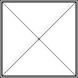
figure 1. (100mm x 100mm)
Using a centre punch and a hammer, centre punch the first drill point in the metal at the precise centre of the cross. This is the centre where you will drill all five plates at the same time. Now place the other 4 plates under the plate you have just centre punched. While using a clamp or metal vice of some description, clamp all of the plates firmly together.
The plates should be flush an equal on all sides, with all plates being as symmetrical as possible although not critical. No plate should overlap or stick out sideways from any of the other plates once they are all clamped. Now using the 5.5 or 6mm drill bit, drill through all 5 plates at the same time.
You will need some physical pressure and an oil lubricant to drill through all the plates in one process. Important, once you have drilled through all 5 plates, you must undo the clamp and remove any 2 plates away from the rest of the stack.
Do not re-drill these two plates. Replace the clamp back onto the stack of 3 plates and tighten firmly as before. Now change the drill bit in the drilling machine and fit the 12.5 mm drill bit. You are now required to redrill these 3 clamped plates only out to the larger 12.5 mm drill bit size.
These 3 plates have larger holes as these holes will fit the 12.5mm x 0.75 - 1mm wide collar on the nylon spacers. Don't worry if you don't understand this collar function just yet... (see figure 4.)
If you wish to go to additional expense you may get the 5 plates lathed round to get a more professional look and finish to your plates. This is totally optional and left to your own preference.
The more plate area the better the system works. Lathing the plates round only improves the cosmetics, which is at a small but negligible expense to the overall operation of the unit.
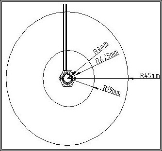
figure 2
If you have purchased the nylon or acrylic as one large block then you will need to cut the spacers from this larger block of material.
Using a pencil or texture, mark the larger block of acrylic or nylon into 40 x 40mm squares.
As described previously, mark across the diagonals of each small square and centre punch the centre the cross only of each of the small squares. see figure 3.
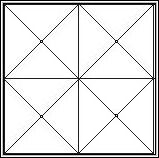
figure 3. (4 @ 40mm x 40mm )
Now fit the 40mm holesaw (with 6mm drill bit) into the drilling machine. Important, be sure that the drill bit in the centre of the holesaw is 5.5 or 6mm diameter, as the centre of the spacer/collars are fixed at this 5.5 - 6mm diameter. Align the holesaw drill bit to the centre punch mark of each square.
Drill through the acrylic/nylon until you have gone right through with the holesaw. You have now created your first plate spacer. Carefully remove the cut spacer from the holesaw cutting blade and continue on cutting the rest. The dimension of each spacer should equal ~38mm x 9-10 mm (x 6 mm hole in the centre). Repeat the process until all 4 spacers have been drill with the holesaw.
Alternatively, you may also purchase a round rod of 40mm diameter nylon/acrylic and cut the above spacers to 9-10mm thick... Note : drilling the centre hole of this round rod type material is much harder when trying to locate the drill bit in the absolute centre.
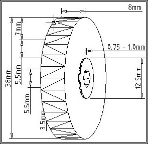
figure 4. (3 of the 4 spaces. )
Once you have all the spacers cut out you will need to modify only 3 of these spacers to hold the 3 middle plates in the centre. The 4th spacer does not require a collar.
These 3 collars prevent the plates from making contact and shorting out with the 75mm x 6mm main fixing bolt of the unit. A 12.5mm x 0.75 -1mm collar will be lathed onto the face of each of these 3 spacers. See figure 4 above for the collar dimensions.
Making the miniature lathe for the job:
Obtain a 6mm dia x 50 mm long bolt with 2 nuts. Cut the head of
the bolt off as close to the head as possible. Now place the bolt
in a hand drilling machine with the cut off end foremost in the
chuck.
Tighten the bolt into the drill chuck securely. Place the first nut on the bolt about half way down the threaded shaft of the bolt in the chuck. Now place one of the 3 nylon/acrylic spacers on the bolt and secure with the second nut. Tighten the nuts firmly, but not overly tight, with a spanner.
Secure the hand drilling machine in a wood vice or similar clamping utility and fix the machine firmly. Turn the drilling machine on and fix the power button with a rubber band to stay on for the duration of each job. With a block of wood clamped securely to the bench top as a cantilever, carve away the nylon/acrylic spacer face with a sharp chisel or sharp screw driver.
You may like to remove a small checkout or mortice the width of the chisel from the block of wood cantilever. This will allow you to maintain firm control over the tool while lathing these collars. (see figure 5.) Start at the edge of the nylon or acrylic spacer and work your way into the centre. You must leave the centre section with a 12.5 mm x 0.75 -1 mm deep collar .
This collar is the main object of importance that you are trying to accomplish with this exercise. This is the collar that holds the plates centre most on the scrubber unit.(refer to figure 4.)
With out this collar the plates can fall away and short out on the main centre fixing rod of the assembled unit, which may burn out your battery charger or power supply.
You should not make the depth of this collar any more than the thickness of your stainless steel plates, as the plates will not tighten up, which will leave the plates flimsy and prone to cause problems.
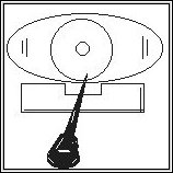
figure 5. (Drill machine used as a mini lathe.)
Ok, once you have all the spacer collars lathed out you will need to modify one more of these spacers to hold the centre electrode in the centre position on the middle plate of the unit. This centre spacer must be one of the spacers with the lathed out collar as done above. Turn the previously lathed spaced over and put it back on the mini lathe then tighten the locking nuts.
Now, starting at the outer rim of the spacer come in 7mm and lathe a groove 2mm deep by 3-5mm wide. This groove is where the centre electrode gets looped around and presses against the centre plate. Do not make this groove too deep, else the 2.5mm dia electrode will not contact the middle plate with firm pressure when the overall main fixing bolt is tightened.
This groove prevents the centre electrode from falling away or making contact with the 75mm main fixing bolt of the assembled unit. The centre spacer is the only spacer to get this extract groove.
You will also need to use a small round file to file an extra vertical slot coming from the newly lathed groove to the outer rim of this centre spacer.
This is were the centre electrode shaft comes through the side of the centre spacer. This vertical slot will be 7mm long by 2.5 mm wide/deep into the spacer material.
The vertical slot depth is not critical, as this slot can be deeper than the 2mm previous groove. See figure 6 for the centre spacer dimensions.
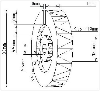
figure 6. (Grooved back of the centre spacer only. )
Before we can bend the ends of the unit electrodes, we must remove the flux off the welding rods; therefore exposing the stainless steel wire underneath.Using a hammer an a hard surface, hit the outer flux off the welding rod wire.
Do not hit the welding rod to hard else you will bend the rod and form it out of shape. Once you have removed all the flux off the wire gently rub the wire to a shinny finish with some 200 grade sand paper. Now the ends of both wire electrode rods are ready to be roll into shape.
The outer most electrode has a half bend the diameter of the 6mm main fixing bolt. By using two pairs of wire pliers you can form the electrode around any 6mm diameter bolt.
Do not use the main fixing bolt for this process as you may damage the thread of this bolt. The end of the centre electrode progresses 90 degrees more an is looped into a full circle.
The end of the centre electrode is formed around a larger 19mm diameter bolt or rod. The inner diameter must be slightly bigger or equal in size to the inner groove on the back of the centre spacer.
A little time and perseverance will see you succeed in forming this centre electrode circular loop. See figure 7 for electrode end loops.
figure 7.
Once all the materials are machined and cleaned of manufacturing errors and general grime, you are ready to assemble the unit. Assembly of the unit is straight forward. You should have 5 plates in total, 3 with 12.5 dia holes and 2 with 6mm dia holes in the centre.
These 2 plates @ 6mm holes are the two outer most end plates. Thread one of the 4 stainless steel nuts onto the end of the 75mm main fixing bolt which should now be cut to length.
Thread one of the outer plates with the 6mm holes right down onto the s/s nut. Thread the first one of the 3 spacers with collars on next.
Next thread a 12.5mm plate on. Be shore that the plate goes over an onto the small lathed collar, and fits snuggling into position.
The centre electrode will have to be placed onto the main fixing bolt at the same time as the centre plate and the centre spacer are put into position.
Repeat the process of plates and spacers until you arrive at the end spacer and the last outer plate.
Remember the last spacer does not require a lathed collar, as the last outer plate has a 6mm hole which by default fixes the last plate into the correct position
You will have to hold the entire assembly firmly with your hands until you can get the final nut into position. Before tightening the last s/s nut you must place the outer electrode under the outer nut as you tighten the whole unit.
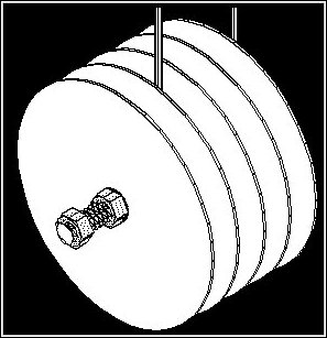
Its not very difficult, and with a little practice as you go it becomes very simple. Refer to figure 8 and figure 9 for any final assembly points and details.
Your final unit should look something like figure 10, but most likely with square plates instead of round.
Figure 8
figure 9
The first rule in testing you unit is to understand what is happening. If possible you should check that the unit has no electrical shorts between either of the two outer plates and the very centre plate.
You can do this with an electrical test instrument called a multi-meter, or you can make a simple light bulb circuit with a 1.5 volt D cell battery , a light bulb and two wires.
Place one wire or test probe onto one of the outer plates; place the other wire or test probe onto the very centre plate.
If the light comes on or there is an error signal or zero resistance with your multi-meter; it is most likely you have a dead short between the two plates or electrodes.
Do not connect power to your unit until you have corrected the shorted plates.Check all plates to see that there is no direct shorts, with the exception of coarse for the two outer most plates. Now understanding the unit.
Starting from the two outer most plates working in toward the centre. The two outer most plates are electrically connected via the main fixing bolt.
This is the correct function of these two plates. The next two inner plates are independently neutral plates an are not electrically connected to any other plates or electrodes.
They are only partially connected when placed in water. The function of how these plates work is known in the electrical field as a capacitive coupling.
The centre plate is of the opposite polarity as the two outer most plates. Ie. if your outer plates are connected positive then your inner centre only plate must be connected negative, and/or visa versa...
figure 10.
Ok, so your sure the unit is functioning correctly with the test meter ? Then it's time now to place the unit in some water and hook up the power.
For the first test we will use a 2 litre icecream container 4/5 full of hot water; taken directly out of the hot tap over the sink or bath. With the power to the unit turned off, connect the battery charger negative lead to the centre most electrode.
Next connect the battery charger positive electrode to the outer most electrode. Now place the scrubber unit in the 2 litre container of hot water.
Standing slightly away from the unit turn on the power. If your battery charger is fitted with a meter you should see a small amount of needle movement.
The needle on the charger meter may read up to around 1 or 2 amps. It really depends on the condition of and the mineral content in the water.
If the battery charger starts to get hot for any reason; switch it off immediately an assess any problem.
Never let the battery charger leads or the electrode contacts short together or touch each other.
If you are a novice or just newly into this field of research you should never ever use a metal container or steel drum to sit your unit in while it cleans the water.
The metal container provides a dead short through your water scrubber unit, which could damage your power supply.
If all is well you should immediately see hydrogen and oxygen bubbles forming on the surface of the plates.
Hydrogen comes off the negative plates while oxygen comes off the positive. These bubbles are very beneficial in killing most bacteria in the water, particularly the oxygen, for oxygenation of water kills most bacteria as well as benefiting our own health.
If you use a bit of ingenuity you can catch these bubbles and burn the hydrogen. But be extremely careful, because hydrogen in the presence of oxygen is extremely explosive.
If you operate your water scrubber in a closed environment you should never allow any build up of this explosive gas mixture. Some bubbles will form on the top of your water as your unit does its job, but they will eventually burst harmlessly into the air.
As a further precaution you should avoid smoking or lighting matches near the water scrubber while it is in use. It is most unlikely that you will ever have to worry about explosions if you use your unit in the open air. If you seal the unit away in a closed environment then you should take simple precautions to avoid the collection of H2 + 0 gas mixture.
Its a good idea to change the polarity (swap battery charger electrodes over) every time you use your unit.
This will prevent the plates from building up scum and heavy metals onto one set of plates. The technical term for this heavy metal build up is called electro-plating.
If you notice your plates in the centre containing more dirt and grime than the outer plates, then reverse the battery charger leads over and the dirt and grime will eventually remove itself off the plates.
You may also clean your plates with steel wool or kitchen cleaning pads.
You may also soak your plates in mixture of 50/50 hydrochloric acid and water if the plates become to dirty to clean by hand.
If you drive your unit too hard with high current because of dense electrolytes or dense mineral compositions in the water, then the plates can become pitted with tiny micro holes all over the plates.
Try placing a resistor in series with the battery charger electrodes, as this will limit the electrical current going through the unit.
It's best to try an avoid these adverse conditions. Treat your water scrubber with some respect and you will likely get years of service and thousands of gallons of clean water out of your unit...
Once you have your Water Scrubber Unit© working as it should, with small bubbles of hydrogen and oxygen happily rising to the top, you will start to see a conglomeration of dirt and heavy minerals starting to make the water turn a cloudy filthy brown colour, and finally to a disgusting black colour with particles floating on the top.
This black sludge is said to be something akin to the sump oil from an automobile.This dirty sludge and grime function of cleaning the water is perfectly normal for the scrubber unit.
The microscopic dirt and mineral particles are starting to come together and form larger molecules.
Depending on their composition, these larger molecules will either float to the top because the hydrogen/oxygen bubbles carry them upward, or they may become heavy and sink to the bottom of your plastic container. Do not be discouraged by the look and smell of your water at this stage.
After two or three hours (depending on your water) you should see the needle on your battery charge start to drop in current.
This proves that the dirt and minerals in the water are being removed. The amount the needle or current drops depends on your water and what composition of elements are in it.
This may take 3- 4 hours or it may take a lot longer. It doesn't really matter how long it takes.
With some trial an error you will establish the best time for cleaning and charging your water.
You will eventually work out that leaving the unit on for an extra 2 hours does nothing to remove any more dirt and minerals... Like all good analyses, it's best to keep a diary of what you have done an how you have done it.
I would like to hear feed back from people who have done experiments and what modification they have made to improve the overall system.
Once you are happy that the unit has completed its job, switch off the power at the wall and rinse the scrubber unit under running water while scrubbing the plates with a kitchen bottle brush.
If you let the dirt or sludge dry on your unit plates there will be a slightly longer period for the unit to clean the same amount of water the next time around. Now, look at all that sludge sitting on top of your test container.
Remember that clean clear water you thought was clean and healthy when you first placed it in the container ? Makes you take a second look at what you are really drinking doesn't it? Anyway, source a large plastic or wooden kitchen spoon an stir all of that sludge and grime back into the water.
Yes, just stir the whole container full of water and sludge until the whole lot becomes one brown/black looking container full crude oil. Now cover the container and let it sit in a quiet location for some 4- 8 hours.
What will happen is, the hydrogen an oxygen bubbles mixed into sludge on the top of the water will eventually burst allowing the sludge to sink and form a layer at the bottom of the container.
This will force the water to become crystal clear again. You may become quite surprised by this ? Now all you have to do is carefully separate the water and sludge by syphoning or pouring off the clean water from above the sludge layer at the bottom of the container.
There you have it, clean oxygenated charged water ready to drink. The health benefits of this water are numerous.
I have no medical degree and therefore cannot justify the truth in these claims, I will therefore decline to mention such anecdotes.
People may like to form their own discussion group and/or email list to exchange information ?
Cheers, enjoy your water...
G.D.Mutch
16-2-2000
The user/constructor assumes all responsibility for the use or inability to use the above information or machinery listed .
If you are unable to manufacture or find a suitable source for the 5 plate unit described in this text, then I can manufacture a unit with any number of plates and to any reasonable size for you.
All jobs will be quoted and priced as per request. As friendly note, acrylic/nylon and stainless steel materials are unjustly expensive and very hard on machine tools.
As a guide I can manufacture the 5 plate unit described in this text ,100mm x 100 mm square unit, for a price of $126.00 Australian (as @ 16-2-200). A percentage discount applies for larger units or bulk orders...
The unit price quoted here covers the manufacturing of the water scrubber unit only, as described in the above text. It does not include the electrical power supply or battery charger mentioned above. Further costs will be involved if you wish to purchase a power supply with the water scrubber unit.
Please send email to :
G.D.Mutch
email :
pagemaster@rocknet.net.au