
For many Centuries when the discovery of magnetic material had been discovered mankind has been trying to get a permanent magnet to provide rotary motion.
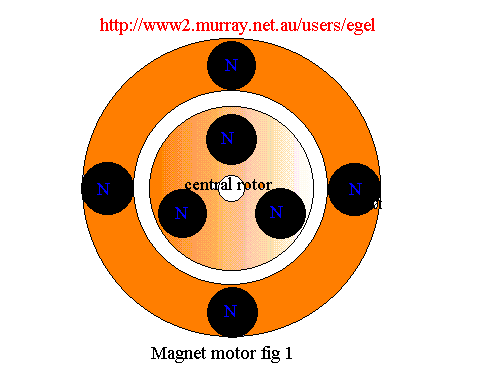
In the above diagram are seven magnets similar to the Tandy round magnets three mount on a rotating shaft at 120 degrees to each other.
On the stator we have four magnets at 90 degrees to each other..
From the above diagram the best we can hope to happen is this magnet motor will align them a to position in the above diagram and stop where they find a magnetic balance.
But the above idea may be of benefit and use some of the magnet repulsion power can be encouraged to promote forward and useful movement.
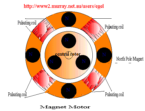
The above is a modified diagram of the first diagram with the addition of four coils so as to produce a pulsating magnetic field in each coil separately or with two coils together so as to produce a pulsating magnetic field the same as the P/M next to it.
In so doing create an unbalanced field in that region that forces the rotor to find a new balanced position further on.
This then continues for each coil in sequence by some switching means maybe a Hall effect device..
This idea has not actually been built but could prove to be viable.
There have been designs similar in concept but tend to have the coil in one position whereas I tend to think that a combination of coils used singularly or in combination would be better.( only testing will prove the better combination)
I believe it would be better if the magnets and electromagnets were to be mounted on a non magnet meta, plastic or wood so as not to decrease the magnetic relative strength of each position..
Due to the excellent work and construction work carried out by Greg Watson and Jean Loius Naudin the possibility of getting P/magnets to do work without additional energy work seems to be closer (their web pages appear at the bottom of this web page and those interested should spend some time check these excellent sites out.)
In Greg Watsons design The main difficulty seems to me is to get the magnets to line up correctly.
The design to me seems to be a magnetic wedge through which a steel ball or magnetic influence ball is drawn through
the wider and less magnetic strong power towards a greater magnetic field.As this happens the ball gathers speed and is carried along a rail and finally ejected at the other end.
If you check out the Jean Louis Naudin site you will see he is as is trying to achieve a rotor device using the same type of idea
His design involves stacking magnets in a semi circle on two sides of supporting supports and a central rotor with
magnetic influence balls at what seems 120 degrees to each other.
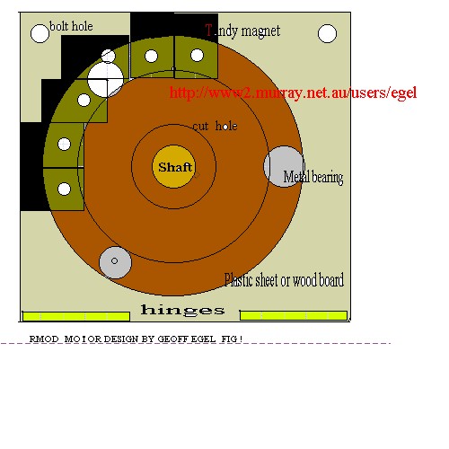
My idea is to mount the magnets on a two flat boards in a semi circular pattern with a magnetic metal backing as shown in the above drawing and then to have hinges at the base of these boards so that they can be mounted as shown below.
At the centre of these boards is a central circular hole large enough to accommodate the hopefully rotating shaft and allow the shaft not to touch the sides of the circular hole when hinge sections are folded together and held in place by bolts positioned at top of the hinged sheets. This would allow experimentation to find best position.
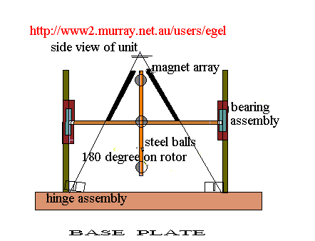
The rotor is constructed in a manner similar to the J Naudin model that being balls mounted at 120 degrees and mounted on a shaft to allow rotation and supported by posts on which bearings are mounted.
Let me know what you think of the ideas and if you have constructed something similar
Geoff

Sites along similar themes
Jean Louis Naudin home page France