The Secret of the Ages Reveled!
How the Great Pyramid was Built
based on the information
and discoveries of Edward Kunkel
Page 1 of 2
The Secret of the Ages Reveled!
How the Great Pyramid was Built
based on the information
and discoveries of Edward Kunkel
Page 1 of 2
 The above image is for reference.
 Before the Great Pyramid was built, the site was a granite outcropping
or rock or whatever you want to call it. The shape and size of this outcropping
before the building of the Great Pyramid is unknown. In the finished
pyramid the granite outcropping protrudes up to a height of at least near
the bottom of the Queen's Chamber. The site is on a gradual sloping
hillside. Uphill form the Great Pyramid is the Libyan Dessert.
Before the Great Pyramid was built, the site was a granite outcropping
or rock or whatever you want to call it. The shape and size of this outcropping
before the building of the Great Pyramid is unknown. In the finished
pyramid the granite outcropping protrudes up to a height of at least near
the bottom of the Queen's Chamber. The site is on a gradual sloping
hillside. Uphill form the Great Pyramid is the Libyan Dessert.
Almost all agree that the two subterranean shafts and the subterranean
room were excavated before the pyramid was built. The simple drawing below
shows the state of construction when the subterranean shafts and chamber
are completed.
 It is the contentionof the Pharaoh'sPump Foundation that the ineffective
barriers in the passages were in reality valves of various types.
These check valves are described elsewhere in this site. IF
the dead end shaft that leads from the Subterranean Chamber is a drain
with a valve placed in it, then all the elements of a hydraulic ram pump
exists, in gigantic proportions!
It is the contentionof the Pharaoh'sPump Foundation that the ineffective
barriers in the passages were in reality valves of various types.
These check valves are described elsewhere in this site. IF
the dead end shaft that leads from the Subterranean Chamber is a drain
with a valve placed in it, then all the elements of a hydraulic ram pump
exists, in gigantic proportions!
 Here is what Mr. Kunkel says about this Subterranean area.
The mechanical element needed to make the Subterranean cuttings
a water pump is a drain and valve.
The mechanical element? - A dead end shaft, cut in the south-eastern
corner of the compression chamber.
It is 52 feet 9 inches long, 2 feet 7 inches wide, and 2 feet,
5 inches high.
Its direction is from true north to south.
Its position is horizontal.
It lies at the lowest corner of the chamber.
Its position suggests, that it could be a drain: but it dead
ends in the rock. Even though it is 105 feet below the base of
the building; it is still high enough from the outside to function as a
drain.
Apparently this dead end has never been examined; with the idea
in mind, that it may be a drain duct.
In 1954, two sun ships were discovered in the rock hewn cavity
at the very southern base of the pyramid.
It is reasonable to assume that the size and shape of this cavity
has been surveyed and recorded. But, such data is hard to come by;
at least for me.
It would be interesting to examine the north wall, and ascertain
the distance from it to the terminus of the dead end. The terminus
of the dead end is about 83 feet south of dead center of the building.
This leaves a space of about 300 feet to its southern base. In short, I
believe there exists a connecting duct, between the dead end, and the sun
ship cavity. Explorers might hit pay-dirt; if they take a good hard
look, at the end of the dead end, and the north wall of the sun ships crypt.
The cutting of this shaft must have been an awful job. - It is
so small. . . . It is only 29 inches high, and 31 inches wide. - There
is very little elbow room. - Maybe a midget crew cut it.
I'll never believe, that its existence is due to over-sight,
or gross error. - I'll never shrug it off, as a miscalculation. I
have too much respect for the ancient engineers for that.
Why all the fuss and todo about a hypothetical water duct?
If such a duct were discovered; what possible mechanical significance would
be interpreted from it? Another question; What if no waste mechanism were
found in the duct?
The answer lies in this simple fact; a waste duct in this
particular area, would be definite proof that the engineers had cut a simple
water ram in the solid rock.
A simple water ram of monstrous proportions.
A ram, which pumps for more water than it wastes.
My guestimate? At least 40 tons for one ton of wastage to a height
of 60 feet; during a time cycle of one minute. Answer; the sun ship
cavity itself may be part of it. My line of reasoning follows this pattern.
Primarily the cavity was cut for use. After it was no longer needed, the
sun ships were installed. Why not decorate it, touch it up a bit,
with some regal trappings?
What if no duct were found at all? - I'd say they overlooked
a good bet. - My alibi in this case; they learned they didn't need it;
which after all, does not make a bit of sense.
I have believed from the very first, that this tube is part
of a drain, and that its outlet is sealed, in just as clever a fashion
as the ancients managed to conceal other openings. It is utterly
fantastic to believe, that the ancient engineers overlooked this common
device; a drain that can be opened and closed at will, and thus; employ
the same mechanics of the common ram.
During the early stages of construction, the use of a controlled
drain would eliminate the need of a fire, to create a vacuum. - Simple
ratios indicate, a negligible amount of waste water to the amount pumped;
whereas the modern ram wastes more than it pumps. I predict, that
one or more baffle walls will be found I the tube, the function of which;
is to slow down the high velocity of discharge, and ease the shock exerted
on the waste valve.
What will the drain valve look like? - It will be a "door
with pivots." We call them butter-fly valves. They are
easy to open and close, and are operated by a handle. Pairs of holes
with proper seats to fit this type of valve are found in the tube, leading
to the upper diagonal. - And none, for a moment doubt, that these seats
and holes are for this type of, "door."
A short distance down in the solid rock of the lower diagonal,
is a tiny offset, "wherein," says Petrie, "hung a door that swung inward."
A pair of eight inch round holes are found here, one in the ease wall and
the other in the west wall. Adjacent to these round holes, is granite
masonry. Giving this mechanical element an interpretation in hydraulics,
is, check-valve. The holes support a round shaft, and the granite
masonry is the valve seat.
End of excerpt
(the above image will soon be replaced by an
animated image to show how the hydraulic ram works)
The above picture shows how the underground cuttings were used as a pump.
They were doing what every engineer must do before he undertakes such a
project. The machine comes first, and in this case it was
a water pump. These subterranean cutting formed a hydraulic ram pump.
Now we will look at:
How the pump was used to BUILD the Great Pyramid!
Below is a top view of what we have so far. The image is supposed
to show a mound of rock with a passage in the center that leads up from
the subterranean chamber. (Please excuse the poor art work!) All
of the subterranean passages and subterranean valves are finished and the
colossal hydraulic ram is ready to go!
 If the hydraulic ram pump pushes water upthe central shaft it will be wasted
because the water will just flow down the hill side. At this stage
parabulious walls were built around the building site. This created
a catch basin for the water. Below is a view of the parablious wall
in place with the catch basin filled.
If the hydraulic ram pump pushes water upthe central shaft it will be wasted
because the water will just flow down the hill side. At this stage
parabulious walls were built around the building site. This created
a catch basin for the water. Below is a view of the parablious wall
in place with the catch basin filled.
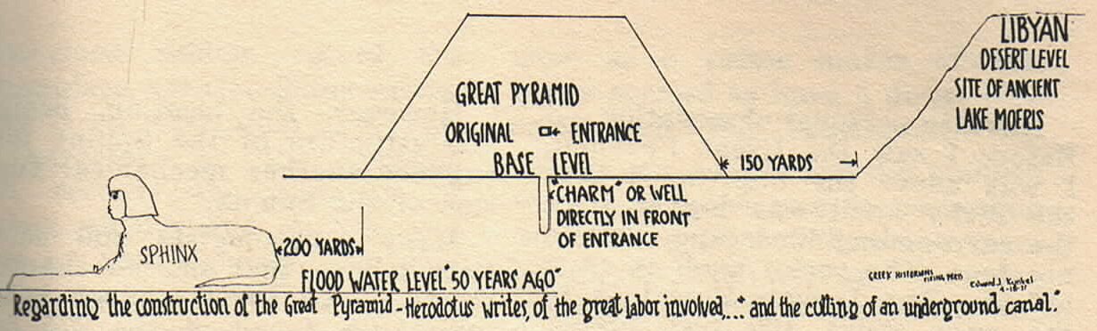
 Near the base of the Great Pyramid, to this day can be seen, parabolus
walls made of earth, which surrounded the building. The walls form
a rectangular basin. It looks like the remains of an ancient catch
basin, or reservoir. And the 14 foot vein of river silt, which is
found in it, is mighty convincing evidence, that in ancient times, this
rectangular enclosure held water, and formed a pond 180 acres in area.
And the little rocky knoll, upon which the pyramid stands became a little
rocky island.
Near the base of the Great Pyramid, to this day can be seen, parabolus
walls made of earth, which surrounded the building. The walls form
a rectangular basin. It looks like the remains of an ancient catch
basin, or reservoir. And the 14 foot vein of river silt, which is
found in it, is mighty convincing evidence, that in ancient times, this
rectangular enclosure held water, and formed a pond 180 acres in area.
And the little rocky knoll, upon which the pyramid stands became a little
rocky island.
The engineers had already built a pump. The next step is to build
a device to use it, otherwise pumped water would pour down over the sides
of the knoll, and be wasted.
Try to envision if you will, the rocky knoll, high above the Nile,
before a single block was set. It must have been a bleak, bare, gray
mound of limestone, It was not flat. It must be leveled off.
To use the water, it must be caught. The simplest device to catch
it, is a ditch.
Once a ditch was cut and filled with water, it formed a perfect device
for a leveling operation. Water would pour from the ditch at the
lowest contour of the rock. This lowest contour determined the elevation
of the base.
Five hundred chislers could be put to work at one time, and whack the
base down to a uniform level, P.D.Q. The still water, in the ditch
would be their gauge, and simplify surveying operations.
With simple water control devices installed in the ditch, the 16 ton
casing stones, these precision cut, beveled beauties, could be floated
on a barge with brackets on the side; Brackets not unlike the modern
fork lift, and lowered gently into place for a long, long rest.
For countless centuries they have evoked the awe, the admiration, and
conjecture of all men. With profound silence, they have cried out
through the ages, the glory of a vanished race of artisans, engineers,
scientists and kings.
But how did the Ancient Engineers get the blocks
up to the site of the Great Pyramid???
For the answer to that please go to  Page 2
The Great Pyramid Water
Pump | How the Great Pyramid was Built
Home | FAQ
Links
Please send comments or questions regarding these web pages to
Pharaoh's Pump Foundation
Copyright © 1998 Pharaoh's Pump Foundation
My URL: http://surf.to/ppf
(ppf stands for Pharaoh's Pump
Foundation)
Page 2
The Great Pyramid Water
Pump | How the Great Pyramid was Built
Home | FAQ
Links
Please send comments or questions regarding these web pages to
Pharaoh's Pump Foundation
Copyright © 1998 Pharaoh's Pump Foundation
My URL: http://surf.to/ppf
(ppf stands for Pharaoh's Pump
Foundation)