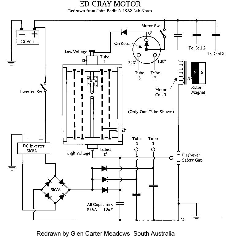

SECTION 6 Principles of the Glo-regulator The glow discharge regulator uniquely amplifies pulsating high-voltage and converts it into a steady stream of electrical energy. It has an axial, negatively charged cathode wire that extends the length of the cylinder. The anode is made out of an aluminum cylinder that is positively charged. Its cathode is a thin tungsten wire. Glo-regulator - Figure 6 In the diagram shown here negatively charged air ions are formed at the negatively charged center cathode wire. Positively air ions are formed at the positive anode cylinder. When a surge of electrons flow through a glow regulator they are added to the negative ions that sit on the cathode. They are now attracted to the positive anode cylinder and a few milliseconds later the positive ions are attracted to the negatively charged center cathode wire. This characteristic has the effect of suppressing any inductive kick back from the loads that are feed through this component. Inductive kick back results in wasteful heat losses. A number of negative ions recombine with the positive ions. This generates an intense burst of free electrons. Moray called this process "dissociation." The "sea electron" model supports this effect. The electrons that are added to the cathode ions will add amperage to the output circuit to which it is connected. Henceforth, the equation E X V = P is used in this system. Where, "E" represents electrons (amperage), "V" voltage (ionic difference) and "P" is the power generated. I am fully convinced that my Glo-regulator is a refined version of Edwin Grays’ conversion tube described in his US Patents No. 4,595,975 and No. 4,661,747. Chauncey J. Britten also describes a similar component in his US Patent No. 1,826,727. Mr. Britten's component appears to be a prior variation of my recent Glo-regulator design. Britten's regulator was said to have lit up his home in 1930 according to a local newspaper article of that time period. Russian scientist Alexander Chernetski experimented with what appears to have been a type of Glo-regulator. It is said that he got up to five times more energy out of his device than what he put into it. Plans were made to commercialize the invention but like the Moray, Gray and Britten devices it never made it to a commercial product. The Glo-regulator is not to be confused with a current rectifier. The Glo-regulator prevents ions from flowing back to the power source. It is an 'energy dam' for the lack of a better description. Both negative and positive ions can flow through this component. If the Glo-regulator is supplied with alternating negative and positively charged ions there is a flow of alternate charges going in one direction rather than a charge blocking effect. This is why Moray stated that "the valves are not rectifiers in the sense that they operate as radio valves in changing AC or HF to DC. Glo-regulators have an actual valve action in stopping the 'flow' of energy in one direction. Its function may be thought of as an oscillatory action similar to the waves of the sea, without rectification, from returning to the outer circuit." 209, The Sea of Energy, 5th edition. This rather cryptic language now makes sense having a Glo-regulator valve in hand. By means of the Glo-regulator new and wonderful electrical effects can be obtained. With the type of current that it produces electromagnets can be strongly energized. This means that electric motors can be made to run with efficiencies that have been unheard of until now. Communication systems using this current could obsolete present day radio transmission. Electrical power transmission and its generation could also receive a fresh new start. The possibilities are mind boggling. It would be an honor to be able to offer humankind this technology. It is my goal to build and bring devices to market that will operate on this new type of electricity that Tesla and Moray called "radiant energy." It was this form of energy in its unrefined form that was generated by Tesla's Magnifying Transmitter, also known as his DC transformer by his lab assistants up in Quebec Canada. Tesla's last ten years of his life, 1933 - 1943, contrary to popular belief, were his most productive years in his private laboratory located on Canadian soil. This was communicated to me through his last known living assistant, Arthur Mathews, before passed away in 1986. He also revealed to me that special primary batteries with replaceable zinc electrodes powered Tesla's electric car. This car also had a "fluid transmission" and could travel at 90 miles per hour. The electric motor could run on the batteries for three hundred miles before you had to pull over to attend to the batteries and then you were on your way for another three hundred miles. There were enough spare parts in the trunk to run this car for one year! The performance of this vehicle seems to be impossible. However, the characteristics of a unidirectional electrical current consisting of short duration high-energy spikes will permit many seemingly impossible innovations. SECTION 7 Edwin Gray's Energy System
The overall efficiency of the Gray device is extremely high. From one of his company press releases we are told that it will power loads four times longer in comparison to a standard DC to AC inverter power supply. This particular press statement indicates that he was planning to market a device that outputted a 6Khz frequency, as compared to the standard 60Hz frequency coming from the public utility power grid.
Both the Moray and Gray energy systems harness a very old source of energy in very unique ways. They are the solution to our power needs using an inexpensive renewable energy. The advantages over other systems are many. The World is indeed moving at a suicidal pace, we need this technology more than ever. It will light lights, run motors and electrical appliances.
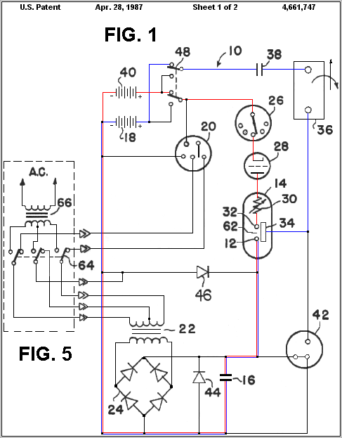
Getting back to the Gray device. It is a fact that when you put a high potential current across two opposite elements, ionization will occur between them. The high voltage elements 12 & 34 develop a pre-discharge plasma glow between them. This is a given unless the elements were to exist within an extreme vacuum environment. The Gray conversion tube acts no differently. When a glow pre-discharge is present the tube is switched in the on mode and current flows. Without this ionization between the cylinder and rod in the conversion tube no current will flow through the load.
Discharge occurs across the spark gap 62 once this capacitor reaches the breakdown voltage of the gap. Once the arc is broken it begins to recharge the cycle repeats and the cycle repeats so long as the batteries remain charged. The current path flows along the red wire shown in Figure - 7. Ionization drops in the conversion tube 14. The load current is halted. When this discharge takes place the anode 12 is heated. Most of you are acquainted with the fact that the space between a hot filament emits electrons and a cold electrode by which these electrons are attracted is unilaterally conductive. Current can flow only from the hot filament to the cold electrode. It is known that when an electron moves through a magnetic field, whose lines of force are at right angles to its direction of motion, the electron is constrained to move in a circular path. In fact, if the field is made strong enough the electron may be forced to stay in the field and revolve in a circular orbit whose diameter is smaller than the field. If a magnetic field is applied transversely to the motion of the electrons the electrons may be deflected to such an extent as to prevent them from reaching the plate and to constrain them to return to the filament. A.W. Hall of the General Electric Co. was the first to use this principle in highly efficient vacuum tube converter he called a magnetron. The sudden discharge in the converter tube generates an intense magnetic field that very abruptly halts current flow to the load. Directly thereafter the magnetic field collapses. The collapsing field in conjunction with the reappearance of the pre-glow discharge instantly generates an electrical surge of power. This surge is unidirectional and can run motors and light bulbs with extreme efficiency because DC resistance does not limit this type of current and wasteful heat loss is practically non-existent. The output if feed into a tank circuit can produce high frequency currents. Old storage batteries are preferred because they can hold up to high voltage discharges. In time the recovered spark discharge will clean off the sulfur that has formed on their plates.

Edwin Gray Energy System - Figure 7
" Reproduced from Radiant Energy Power Generation" (millenium edition) by Bruce A. Perreault
