

Believe it or not, nearly
everyone you know has at least one induction generator and probably
more That's right! You
say that is impossible... well, read on!
Within every home there are motors that
can be operated as generators. They may not be labeled as generators,
but they will function just the same. These motors are offen called
"squirrel cage motors" and are in washing machines, dryers, water
pumps and other devices too numerous to mention.
 ...............................
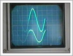
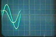
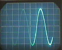
Besides being numerous and cheap, they will generate AC voltage of the purest sinewave. They use no brushes and do not produce any RFI.(Radio Frequency Interference) A motor converted to an induction generator will power flouresent and incandesant lights, televisions, vcr's, stereo sets, electric drills, small power saws and other items.
OK, what is so great about it? There is nothing complicated about the conversion, no weird rewiring, no complicated math...nothing! There are no brushes to wear out.
They can not be overloaded; if too much of a load is applied to the generator, it simply quits generating. Removing the load will usually cause the generator to start again. Speeding up the motor will help if it doesn't start right away.
Yes, but... are there problems? Well, there is no active voltage regulation, but keeping it within a tested load rating can keep it within any voltage parameters that you set. I feel that a voltage range between 105 and 126 volts is perfectly reasonable.
A motor converted to an induction generator will not start another squirrel cage motor unless that motor is about 1/6 of the horsepower of the induction generator. In other words, a 1 horsepower motor used as an induction generator will start a 1/6 horsepower or less, squirrel cage motor.
The generator will not start under a load. Not a problem! You shouldn't attach any load to a generator until it is at running speed. This is actually kind of a fail-safe feature.
So far, that is about all of the problems that I've found and I consider those minor.
By adding capacitors in parallel with the motor power leads, and driving it a little above the nameplate RPM, (1725 RPM ones need to turn at approximately 1875 RPM, and 3450 RPM ones at 3700 RPM) the motor will generate AC voltage! The capacitance helps to induce currents into the rotor conductors and causes it to produce AC current. The power is taken off of the motor power leads, or the capacitor leads, since they are all in parallel.
This system depends upon residual magnetism in the rotor to start generating. Almost all the motors I've tried begin generating just fine on their own, with the appropriate capacitor connected of course! If it doesn't start generating, try speeding the motor up. That will usually get it going. However, it is extremely rare to find one that doesn't start.
If a motor doesn't start generating on the very first try, then apply 120 vac or even 12 or more volts DC to the motor for a few seconds. That will usually work to magnetize the rotor and your generator will start by itself from then on.
I've only found one motor that would not consistantly generate (out of a dozen or so that I've tried over the years) and it was one with a bunch of wiring coming out of it; it may have been a multi-speed AC motor. I had a 120 volt AC relay in the circuit that temporarily added a 200 uf starting capacitor across the permanent 160 uf running capacitor (Using the Normally Closed contacts) to get it generating. When 120 volts was produced, the relay contacts opened up and removed the 200 uf from the circuit. That worked, but it was not dependable. I just gave up on that one.
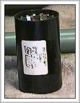
The capacitors used must be the type designated as "running" capacitors and NOT "starting" capacitors. Starting capacitors are used for a very short time, usually less than a second or two, and would be destroyed by being connected across the AC line continously. Running capacitors are designed to be connected while the motor is powered.
NOTE: Make sure the caps say, "NO PCB's". PCB's aren't used anymore for capacitor construction because it was a dangerous chemical composition. If the caps are old, and you are not sure, don't use them. Be safe!
It is necessary to experiment to find the best value of capacitance to get one working. Start with about 150 to 200 uf for motors 1 horsepower and under. More capacitance equals more voltage output. The final value should be able to produce about 125 VAC when it is putting out 60 hertz with no load. Then plug in100 watt light bulbs until the voltage drops to what ever lower limit you set. Mine will do about 1050 watts before dropping to 105 VAC.
 ............................
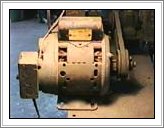
In the following example, I used a 1 horsepower motor from a Sears water pump that I bought at a junk yard for $10.00. This motor was capable of operating off of 115 or 230 volts at 13 or 7 amperes respectively.
Motor: A. O. Smith 1 Horsepower : 115 / 230 VAC : 13 / 7 AMPS : 3450 RPM
Capacitor: 200uf 330vac. This was made by paralleling 4 capacitors that were 65uf, 35uf, 50uf and 50uf. All of these were rated at 330vac or better. All test results are from this capacitor set. (NOTE: The final version of this generator has 225uf of capacitance.)
Output Capability: This Induction generator has an no load voltage of 125.9 VAC at 60 hz. The generator successfully powered 1050 watts of lightbulbs with a voltage drop of 10.9 VAC to a full load voltage of 105 vac. During the power test, the generator was driven by a 1.5 horsepower electric motor and there was a loss of RPM when the load was increased. I attribute some of the voltage drop to this lack of driving power.
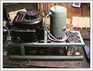
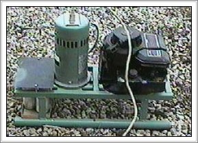
The ex-motor, now an induction generator is driven by a well used 3.75 HP B&S lawnmower engine. A total of 950 watts of lights were ran for about 15 minutes with the generator only getting warm. The voltage went from 126 volts open to 110 volts AC under this load.
Notice the capacitor set-up. Here I am trying a suggestion found in an old article, which stated that it is possible to use DC electrolytics connected in series, + to +, and - to - in an AC circuit. I have 4 capacitors rated at 850 uf, 400 VDC in series, for a total of 225 uf @ 1600vdc . The connection is like this:
AC Lead to motor 0----+||------+||------||+------||+----0 AC Lead to motor
Will it work? They seem to be doing just fine, with no sign of heating at all. If they fail or deteriorate, I'll post the info here on the web page.
 ...................
Make sure you get a reliable gasoline engine. Nothing is more frustrating that to have to fight with the engine while you need electricity!
Nearly all the B&S engines that are used on lawn mowers with a direct connected mower blade depend upon this blade to act like a second flywheel for the engine. They have a primary aluminum flywheel inside the engine cover. The aluminum flywheel does not provide enough inertia to work without the blade. The symptoms are backfiring, jerking starter rope and difficulty in starting. You will probably have to change the aluminum flywheel to a cast iron one. The cast iron ones are pretty common in horizontal engines that are used in rototillers, etc. Usually junk yards or small engine shops will have them. However, if the generator rotor has enough mass, it may have enough inertia to keep the engine running fine with an aluminum flywheel. Just experiment. Also, make sure the magnet matches the one on the original flywheel; they have either one or two magnetic poles which are very obvious by sight.
Go with solid state ignition if possible. Ignition points were fine in their day, but the solid state magneto's are great!
Make sure the speed governer works and that the engine is cleaned and serviced reguarly.
The small gas tank on these B&S will give you at least an hour of power. If you need longer running time, then find an engine with a larger gas tank. A gallon tank will give you lots of time with a small engine, probably over 6 hours or so before refueling. Check oil levels at each gas refill, etc.
If you experience static on radios or TV's that you are powering by your generator: Sometimes ignition static can be a problem. Rubber boots should be placed over the sparkplug wire so that there is no wiring uninsulated, and then simply cover the sparkplug wire with braided wire and ground it near the magneto coil. Also clamp it around the sparkplug metal base. That will cure it.
Static can be caused by the generator rotor bearings. (I have yet to have that problem!) But, just in case you do: Simply mount a little contact brush against the shaft of the generator rotor and that will successfully ground it and eliminate the static.
A. This motor exhibits an internal resistance of about 1.5 ohms of AC resistance and .5 ohms of DC resistance.
B. The capacitor current is approximately 11 amps. Remember, this current exists whether there is a load or not. However it is not 100% "real power", but it is capacitive, with the current out of phase with the voltage. The current, I, leads the voltage, E, in this case. The reason this current exists is to keep the generator "excited" by inducing current into the squirrel cage rotor conductors. Calculations seem to put the exciting power at around 55 watts.
C. The reactance (Xc) of the capacitor (200 uf) at 60 hertz is 13.3 ohms.
D. The reactance (Xl) of the motor is (3.8 mh) at 60 hertz is 1.4 ohms
E. The capacitance and the inductance, being in parallel, does exhibit a resonance. This frequency is 183 hertz.
F. The engine needs to turn this generator at about 3700 rpm to give 60 hertz output. (If your motor is a 1725 RPM one, then you'll need it to turn at about 1875 RPM)
G. I don't have a clear understanding of exactly why this works... but it does!
I built this device after a few difficulties. Here' what I found out.
Please fee free to post this to the above page, so others won't make the same mistakes ($$).
By the way, your Energy 21 site (at Greenfiedl) is arranged rather nicely.
From article "An Easy to Build and Operate Induction Generator."
I learned several things while building this generator:
1. Make sure of your pulley to pulley ratio! By mistake, I put a 10" pulley on a 5hp B/S mower engine, and a 6" pulley on a 3hp, single phase, pump motor. Upon startup, I immediately damaged the electric motor. It turns out that I blew all the springs out of the starter relay. Since the relay isn't supposed to be in the circuit, I pulled all of the pieces out and threw them away. The main motor coils weren't damage, fortunately. The reason for this mistake? I didn't know the rpm's of the B/S engine. Upon asking around, I found that a Briggs and Stratton engine typically runs at 3400 to 3600 rpm. I am now using 3" to 3" pulleys, as the electric motor runs at 3450 rpm.
2. Make sure your electric motor turns the same direction as the B/S engine. Well, here we go again.... I took my electric motor to an electric motor place, to test out the generator theory. We hooked up another electric motor to mine, pulleys and rpm about the same. We fired it up. darn, it wouldn't work! My partner said, "this can't work anyway. There's no way you're going to get voltage out of this! You can't get magnetism out of the armature to run this." Well, I had him zap the line input wires with a 12dcv battery charger, 40 amp type. We started the motor/generator setup again. We got 1.2vac output. No success yet. At this time we had two 60mf running caps on the generator output, just to see if the principle was sound. My partner said, "nope, it doesn't work." I was really starting to believe him by this time.
3. Make sure you wire the capacitors right. I took my motor home, feeling somewhat dejected. After looking over the original article, I arrived at the conclusion that I had missed something in the capacitor wiring. The diagram in the article showed a bunch of capacitors in series across the motor output. But I now realized this diagram was for Polarized Electrolytic Capacitors, NOT running capacitors! Earlier in the article, it was mentioned that running capacitors had to be in PARALLEL to the motor output. So I hooked up some 24mf, 60mf and 20mf caps to give me about 210mf parallel total, at about 400dcv rating. These caps came from old "street lamps." A local electrician had some surplus ones, as did my partner at the Electric Motor Shop.
4. Make sure your generator rotational direction is correct. Another reason my generator might not have worked at my friends shop is that his electric motor was turning my motor clockwise. On my motor, the label states that the run direction is CCW.
O.K. I got home and proceeded to deal with the mistakes. My B/S engine rotates CCW. Whoopee! My bank of capacitors are now wired wired in parallel to each other. We already zapped the armature, so that should be ok. I put 3" to 3" inch pulleys on the B/S to generator.
It worked! Bright as ever. Still haven't finished wiring breakers and plugs. But I hope to get better than 2kw out of it. I was told, "don't use a Chinese motor. It wont't work." Well this 3hp Chinese electric pump motor did just fine! the motor cost me $90 at Harbor Freight. I found out later that there are good used motors out there too. I picked up a 3 phase, 330volt motor for $20. Guess I'll try that one later.
I hope this helps you "engineers" out there.
PEA RESEARCH
LeRoy Pea PEA RESEARCH website