
ABSTRACT
A permanent magnet, pulsed DC electromagnet motorgenerator for the production of electric power. The source or input for the
electric power is the magnetic flux of neodymium permanent magnets.
The device consists of a motor, a generator, commutation and a circuit.
The motor consists of permanent magnets fixed to a rotor. The stator
employs pulsed DC electromagnets. The permanent magnets and the
electromagnets are arranged around the rotor and stator opposing each
other. As the permanent magnet rotor rotates, the permanent magnets are
attracted to the iron core of the electromagnets. When the permanent
magnets are slightly passed the center of the electromagnets, a short duration
pulse of DC power is supplied to the electromagnets. This causes the
permanent magnets to be repelled by the like polarity magnetic flux of the
electromagnets. As the rotor rotates the attraction and repulsion of the
permanent magnets and electromagnets provide torque to a common axel
shared with the generator and commutator.
When the primary pulse to the electromagnet ends, the magnetic
field developed around the electromagnet coils collapses. This collasping
electromagnetic field provides a voltage that can be employed to
recharge a secondary battery on the motor side.
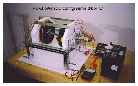
The generator consists of a rotor with multiple permanent magnets
arranged around the perimeter. The magnets are assembled in alternating
polarity. The stator consists of an iron wire core imbedded in an insulated
material with magnet wire coils assembled opposite the permanent
magnet rotor assembly. As the rotor rotates the magnetic flux of the
permanent magnets induce a voltage and current in the copper coils.
The alternating current output of the permanent magnet , copper coil
assembly is rectified to a direct current by means of a full wave bridge.
The direct current is then employed to charge a battery bank.
A commutator is attached to the common axel to provide the
direct current pulse to the electromagnets of the motor stator at the
optimum time for the optimum duration.
A circuit provides the means of delivering power to the commutator
from the primary battery. A new circuit design is being developed to
employ the back EMF from the electromagnet coils to recharge the
motor's batteries.
PM/PEM, M-G
Permanent Magnet / Pulsed DC Electromagnet
Motor - Generator
Summary of Invention
The permanent magnet / pulsed dc electromagnet motor - generator
produces electric power from the magnetic flux of powerful neodymium
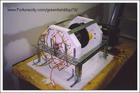
magnets. The PM/PEM,M-G motor consist of two opposing disk, a rotor
and a stator. The rotor is connected to a shaft [ axel ] by means of a flange.
The shaft is mounted to a frame through two bearings that allow the shaft
to rotate while mounted on the frame, one on each side. Attached to the
rotor are permanent magnets arranged equidistant around the perimeter
of the rotor facing the stator.
The stator is fixed in position next to the rotor but independent of
the shaft. The shaft runs through a larger diameter hole centered on
the stator. Mounted on the stator are electromagnets that are
arranged directly opposite the permanent magnets of the rotor.
As the rotor rotates, the permanent magnets come into alignment
with the electromagnets. During this phase the permanent magnets
are attracted to the iron, steel core of the electromagnets. Torque is
provided to the shaft by the magnetic attraction of the permanent
magnet and the iron, steel core. No power is consumed. This is the
Attraction Phase of the Power Cycle. As the permanent magnet rotates
past the center of the electromagnet, a power pulse is fired through the
electromagnet. The like polarity of the electromagnet and the permanent
magnet cause the permanent magnet to be repelled. Torque is provided
to the shaft by means of the magnetic flux of the permanent magnet and
the magnetic field generated by the electromagnet. Power is consumed
for only a brief [ milli-seconds ] period of time. The power pulse is delivered
at the optimum time for the optimum duration by a commutator.
This is the repulsion phase of the power cycle.
Most of the work, power delivered to the shaft in the form of torque,
is done by the permanent magnets. Because power is consumed for
only a brief period of time upon each alignment of the permanent
magnet and electromagnet, very little power is necessary to run the
motor - generator making it highly efficient.
Pick up coils wound around the electromagnet can utilize the collapsing
magnetic field [ back EMF ] of the power pulse to generate a current
that can be employed to recharge secondary batteries.
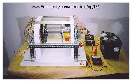
A DC generator is connected to the shaft of the permanent
magnet / pulsed dc electromagnet motor. The generator is
actually an alternator with the alternating current rectified to provide
direct current for charging a battery bank. The principle of operation
of the alternator is the permanent magnets on the rotor provide
magnetic flux which induces a current in the copper coils.
The copper coils are arranged on a solid steel wire core. This reduces
the resistance to the rotation of the permanent magnet rotor normally
caused by the interaction of the permanent magnets and iron core
of the electromagnets.
This is a basic explanation of the working principle of operation
of the PM/ PEM2, M-G. The photos and text supplied to energy 21 by
Mr. Gary Magratten
26901 Ridge Rd.
Willits CA 95490
ph: 707-459-1435
fax:707-459-9298
Please note this information may now be out of date
Check out Gary other article "An apparent succesful reproduction of the Edwin Gray Power circuit with complete details
