

The Exhaust Gas Heat Recovery System is an alternate with superior performance to the exhaust heat recovery system shown on page 8 and page 9, part 22 of the shop drawing-5.
Most other inventions that used engine exhaust heat suffered many short comings.
Where as most previous designs cannot make use of large amounts off engine exhaust hot gas, because the engine exhaust is too hot to be injected in large quantity into the heat exchanger or combustion chamber without the high risk of pre igniting the fuel.
Others have diverted a portion of the engine exhaust into the heat exchanger or combustion chamber.
Unfortunately heat obtained from a portion of the engine exhaust cannot provide a constant stable temperature under all engine loads and conditions.
Others have suffered from laminar flow, which yields poor heat transfer. Others have suffered from high exhaust back pressure, with a drastic reduction in engine efficiency.
Our exhaust Gas Heat Recovery System has over come the above failures and shorts comings other inventions.
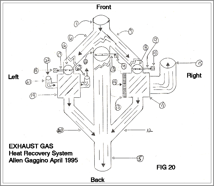
Fig.20
Hot engine exhaust enters middle inlet 1.; when engine is cold the exhaust flow regulator is closed 2 engine exhaust is diverted to the left side inlet 6 and the right side inlet 7 - The servo motor 10 regulates engine exhaust flow through the exhaust gas flow regulator 8 through the heat exchanger 11; and through heat exchanger plates l, 2,3,4,5 and 6 which is shown in figs 25 and 26. Fig 20. Engine exhaust then flows into the right side outlet 12, which flows into the middle outlet 5, which exhaust through the conventional muffler.
Fig 20.
Hot engine exhaust enters left side inlet 6. Servo motor 18 regulates engine exhaust flow through exhaust gas flow regulator 16. Then through heat exchanger plates 1,2,3,4,5 and 6 which is shown in figs 25 and 26. Engine exhaust then flows into the middle outlet 5, Which exhausts into the conventional muffler.
Fig 20 and 24
Coolant source enters the coolant inlet 22; then travels through the left side of the heat exchanger 19. Best shown in Figs 21,22,23 and 24 the coolant flow across the strait finned plates 7.8,9,10 and Lal; extracting heat from the engine exhaust plates 1,2,3,4,5 and 6; Hot coolant then flows through coolant outlet 23; Then flows to the hot coolant inlet 28a and 28b which is best shown in fig 4.
Fig 20.
Fresh air source enters the intake fresh air inlet 14 through the left side of the heat exchanger 11;
As best shown in Figs 2l,22,23 and 24 The fresh air flows across the straight- finned plates 7,8,9,10 and 11; Extracting heat from the engine exhaust plates 1,2,3,4,5 and 6 Then hot air flows through the discharge fresh hot air outlet 15; which is best shown on page A of the shop drawings, part 21 which is the inlet of the high out put fan.
NOTE As seen from above both the heat exchangers can be made from the same plates to produce air to air or liquid to air heat transfer. Also the heat exchangers can be milled, machined, extruded or die cast in aluminium, steel iron, stainless steel and of most other metals, ideally stainless steel is preferred.
As best shown in fig 20 the engine exhaust can flow straight through the muffler or can be diverted to the left side 1iquid to air beat exchanger which produces hot coolant and at the same time it can be diverted to the right side air to air heat exchanger which produces fresh hot air.
Servo motors 4,10 and 18 are controlled with thermostats located in the vaporising chambers of the Fluid vaporising System; which controls the exhaust glow regulators 2,8 and 16; which give total control of both the coolant and the hot fresh air.
NOTE: The catalytic converter is a chemical filter connected to the exhaust system of an automotive vehicle so as to reduce air pollution.
Whereas our Fluid Vaporising system reduces air pollution to almost unmeasurable Levels. Which renders the catalytic converter and most other pollution devices use1ess. Therefore our Exhaust Gas Heat Recovery System can be installed in the space where the catalytic converter once occupied, not to mention the large savings in the cost of the catalytic converter,
Fig 20, Exhaust Gas Heat Recovery System.
1.) Engine Exhaust Gas Middle Inlet.
2.) Exhaust Gas Flow Regulator.
3.) Stainless Steel Rod.
4.) Servo Motor.
5.) Engine Exhaust Gas Middle Outlet.
6.) Engine Exhaust Gas Left Side Inlet.
7.) Engine Exhaust Gas Right Side Inlet,
8.) Engine Exhaust Gas Flow Regulator.
9.) Stainless Steel Rod.
10.) Servo Motor.
11.) Air to Air Cross-Flow Heat Exchanger,
12.) Engine Exhaust Gas Right Side Outlet,
13.) Intake Fresh Air Filter.
14.) Intake Fresh Air Inlet.
15.) Discharge Fresh Air Outlet.
6.) ENGINE EXHAUST GAS LEFT SIDE INLET.
16.) Exhaust Gas Flow Regulator.
17.) Stainless Steel Rod.
18.) Servo Motor.
19.) Liquid to Air Cross-Flow Heat Exchanger.
20.) Engine Exhaust Gas Left Side Outlet.
21.) 90 Degree Ell.
22.) Coolant Inlet.
23.) Hot Coolant Outlet.
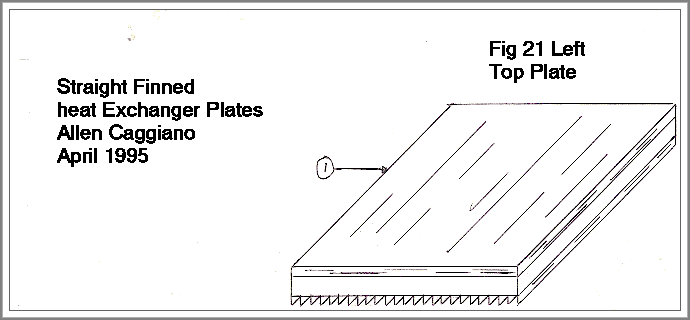
Fig 21.
1.) Top Strait Finned Plate
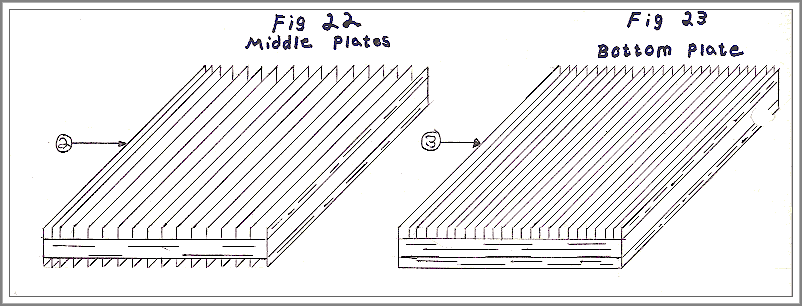
Fig 22.
2.) Middle Strait Finned Plate
Fig 23.
3.) Bottom Strait Finned Plate
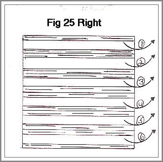
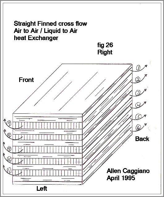
Figs 25 and 26:
In both Air to Air and Liquid to Air heat transfer hot engine exhaust qas all flow from front to back through plates 1,2,,3,4,5 and 6.
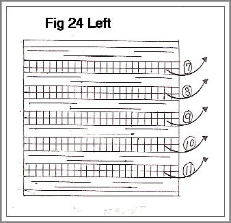
Fig 24.
In Air to Air heat, transfer fresh air flows from left to right in plates 7,8,9,10 and 11
In liquid to air heat transfer coolant flows from left to right in p1ates 7,8,9,10 and 11.
