
Figure 1.
| 25.5 | 45.9 | 66.3 | 86.7 |
| 30.6 | 51.0 | 71.4 | 91.8 |
| 35.7 | 56.1 | 76.5 | 96.9 |
| 40.8 | 61.2 | 81.6 | 102 |
Unbalanced Square/Matrix
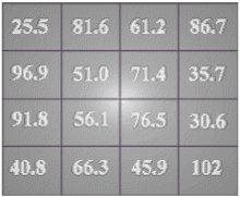
| 25.5 | 81.6 | 61.2 | 86.7 |
| 96.9 | 51.0 | 71.4 | 35.7 |
| 91.8 | 56.1 | 76.5 | 30.6 |
| 40.8 | 66.3 | 45.9 | 102 |
Balanced Square/matrix
With the square matrix of figure1 all line row, column and diagonal values = 255. No matter which way you add all the columns, rows or diagonals they will always add up to the single line value of 255. Also the 4 inner cells ( 51.0, 71.4, 56.1 & 76.5) all add to 255. The 4 outer most corners of the1st.outer ring (25.5, 86.7, 40.8 & 102) also add to the value 255. This function then creates a centre cross over the square/matrix when viewing only these associated values.
I/We normally don't use decimal placing in a square matrix. But in the above matrix of figure 1 we are using a dimension value which was taken from an actual physically measure. Stainless steel piping comes in 'outside diameter' values very close to the values expressed in the matrix. I wanted absolute accuracy to allow others to understand or be able to modify from these values. If I where using physical material volume and not measurement math, I would use whole values in the matrix. I could still use whole math by simply removing the decimal point of the matrix values and replacing the decimal point when I derive the new cylinder physical values from the matrix.
If we use these values in a simple metric coordinate system we can apply millimetre postfix to these and can then apply them as the diameters, length and thickness of the cylinders. With hind sight, there are four cylinders in the Joe Cell, therefore there needs to be four (4) individual values, hence the matrix must be 4 x 4. Because we are also using volume (3D), each value must exist on both the X & Y planes, thus the reason why we use the diagonal. I will try to explain further why I believe this X,Y, Z 3D functions at the end of this document.
We can convert the above diagonal values directly to the
metric coordinate system.
So the values now become :
We now know the 'line value' of the balance square is 255. This can be used as the constant length of each cylinder which equals 255mm
So the value becomes :
The wall thickness of each cylinder (pipe) may be taken from
the ratio of the diagonal values.
Starting from the smallest inside cylinder working out to the
largest outer cylinder. That is 25.5/5.1 , 51.0/25.5 , 76.5/51.0
, 102/76.5 (See figure 2 below.)
![]()
I guess you could try to average these above values and use
them as a constant cylinder thickness.
(5 + 2 + 1.5 + 1.3 ) / 4 = 2.45 mm . I'm experimenting with a
constant 1.5 mm thickness.
Most stainless steel pipe sizing and grades come with a constant ratio of thickness eg. 1.5, 1.75, 2.0 an so on. You may like to try an experiment with different constants or you may use the above ratio if you desire. There is another ratio you could apply to derive the above cylinder thickness, but it brings in the hypothetical next cell value from the above square. (See figure 3 below.) The black border around the 127.5 value designates the hypothetical next diagonal cylinder value.
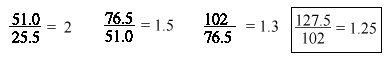
If the constructor is using the hypothetical next cylinder
value, this will give the cylinder ratio values as : 1: 51.0/25.5
2 : 76.5 /51.0 3 : 102/76.5 4 : 127.5/102.0 [127.5 = hypothetical
next cell value.] I have only mentioned the above math here in
case people wish to try it ?
The Line value of the Matrix is 255.
Total Summation value becomes 10 x 255 = 2550
This value can be converted to the Hertz frequency :
This cell might or at least should give out a frequency or pulse at 2550 hz.
Some may like to check this frequency against the harmonics of
the vehicles ignition coil. The now mathematically tuned cell may
work better or worse with resonance of the ignition coil ?
Using the values above we can tabulate the following:
| Cyl. | O/Dia.mm | Len. mm | Thick mm | In/Vol. mm3 |
|---|---|---|---|---|
| 1 | 25.5 | 255 | 5 | 48116 |
| 2 | 51.0 | 255 | 2 | 442410 |
| 3 | 76.5 | 255 | 1.5 | 1081943 |
| 4 | 102 | 255 | 1.3 | 1978804 |
The above Joe Cell matrix could have just as easily been worked out on volume. I leave this up to other people to experiment with the different values an matrices.... I hope the above matrix material is simplified enough for all people to understand. Please share your findings with all other people, and also don't forget to share your findings with me as well!...
As I believe the Natural order of the 3D universe is the balance of two forces (binary). The 3rd state could be the differential summation point, balance zero point or rest state of these two opposing forces. To have something exist it must be present on the X plane as well as exist on the Y plane (binary). When these two forces meet or combine by sum difference or force charge they force the third plane Z into existence. By two natural forces combining the energy must go some where, so it moves at any angle on the Z plane. So as I believe binary then becomes trinary (3D). This is also evident with matrices: as the X & Y plane move/intersect they create the diagonal Z plane. So we can then represent a frame of motion (matrix) on a 2D sheet of paper as a map of 3D. So I therefore believe Searl may also use the left diagonal for this reason.There is also a mirror image of two triangle halves with in all matrices.
I case people have not noticed: all square/matrices have two triangle halves that make up the total square. The upper triangle is the mirror image opposite of the lower triangle. The triangles usualy separate along the left diagonal. Using any unbalance square/matrix, the right upper triangle is alway greater in sum value than the lower left triangle, until you balance the square. At times you may need to understand this mirror image function to be able to apply it in mapping a matrix to reality system.
People may use, distribute, copy, print or hyperlink the above Joe Cell Matrix material as they so desire, provided they fully acknowledge the original copyright of the author G.D.Mutch and those people concerned below:
Let us all work together for a cleaner more content world for all...
Good luck with your Cell...
G.D. Mutch
Rockhampton .Qld. Australia.
Email : pagemaster@rocknet.net.au
ICQ#64918008
Acknowledgments:
Any and all square Square Matrices when applied to the Joe
Cell is Copyright© material 1999, by G.D.Mutch.
The 'Law of the Squares' principle is Copyright© material of
J.R.R.Searl.
Full acknowledgment to Prof.
J.R.R.Searl.
The Joe Cell is technology is Copyright© of Joe Blow. Australia.
Usual Disclaimer :
The author G.D.Mutch makes no claim as to the correctness and
functional use of the matrix with in the application to the Joe
cell. The above information is offered as experimental
information only. The user or constructor accepts all
responsibility with the use or inability to use the above
information.