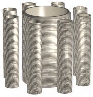


For anybody new to the area of matrix mathematics the following is an evaluation of Alfred Hubbards nine(9) coil alternative energy generator. The author G.D.Mutch has reviewed the a sample of Alfred Hubbards material an arrived at the conclusion that Hubbards technology can be applied to matrix mathematics, which in part is very similar to J.R.R.Searls 'Law of the Squares ©'. The following material will show people how Hubbards design is first formulated into a balanced matrix and then transformed out of the matrix into physical mathematical ratios...
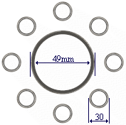
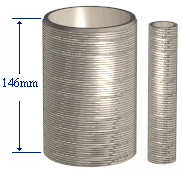
Hubbards dimensions on the nine(9) coil transformer design:
 Top view |
 Side view |
|
|
figure 1.
The dimensions in the table of figure 1 are taken
from Hubbard's actual nine(9) coil design.
Hubbard used a multiply ratio of 5.75 formulated from his
knowledge of the Golden Section. Example 49/30 = 1.6333. Hubbard
stated that his nine(9) coil design above stepped up the output
power compared to the input power by a ratio of 3:1.
The author will now transform the values of
Hubbard's nine(9) coil design of figure1 into a 3 x 3 balanced
matrix. The 8 Coils around 1 inner coil equates to 9 coils which
can be transformed into the 3 x 3 matrix below (see
figure 2).
Matrix = 147 Figure 2. |
* Hypothetical optional 3rd Coil. Figure 3. |
The above matrix of figure 2 has a sum line value of 147. No matter which way you add the rows, columns or diagonals the line value will add to 147. The following values tabulated in random order are then derived from the balanced matrix . These tabulated values are the actual physically wound coil dimensions from which you can build the Hubbard nine(9) coil energy transformer device.
{* This is a hypothetical coil added here by the author. See below text for more information.}
| Centre [ 49] | Turns | Notes |
|---|---|---|
| Centre x 4 | 196 | Hubbard's original calculation |
| Centre x 6 | 294 | Hubbard's original calculation |
| Centre x 8 | 392 | * Alternative calculation |
| Centre x 10 | 490 | * Alternative calculation |
| Centre x 12 | 588 | Hubbard's original calculation |
| Centre x 14 | 686 | * Alternative calculation |
| Centre x 16 | 784 | * Alternative calculation |
figure 4
(* Denotes alternative calculations that could be used in actual coil designs.)
NB. Hubbard is obviously using binary in his calculations...
To derive the copper wire gauge from the matrix you simply divide the turns (see figure 4) by the line value/cylinder length 147mm. Example, 147/196 = 0.75 mm wire diameter. Knowing this last formula we can now construct a table with multiple choice coil dimensions for any derived wire size. (see figure 5)
By using the matrix of figure 2 we have derived the optimal mathematical ratio values from which we can design the actual coil dimensions. Recapping, from the matrix we have derived :
We may therefore tabulate all the values in the above steps into one easy to read table.(See figure 5) You may than use this table as a quick reference to build any coil from the desired wire size.
| Wire size mm | 0.186 | 0.214 | 0.25 | 0.3 | 0.375 | 0.5 | 0.75 |
|---|---|---|---|---|---|---|---|
| Turns per 1 cylinder | 788 | 686 | 588 | 490 | 392 | 294 | 196 |
| Length @ 30mm dia. | 74.267m | 64.653m | 55.417m | 46.181m | 36.945m | 27.708m | 18.472m |
| Length @ 49mm dia. | 121.303m | 105.601m | 90.515m | 75.429m | 60.343m | 45.257m | 30.171m |
| *Length @ 68mm dia. | 168.339m | 146.549m | 125.613m | 104677m | 83.742m | 62.806m | 41.871m |
figure 5.
* Denotes the optional 3rd coil dimension. As I am lead to believe, this third coil is not in Hubbard's original nine(9) coil design. The author has added this coil here to allow research into its possible further use as a power multiplying coil.
Hubbard stated he could use copper wire of different diameter gauges to complete one totally wound coil. The lengths shown in the above table equals the total copper wire length in meters that you will require to wind one complete coil onto the cylinder/former....
Using the coil dimension table :
To use the above table of figure 5 simply read down the vertical
column of the desired wire diameter/gauge, then read off the
Turns, and the Total Length of wire for each of the 30mm,49mm and
68mm diameter coils. Example, if you chose to use a wire gauge of
0.75mm you would use the following values :
The values listed above represent one totally wound coil per cylinder. Hubbard uses 8 coils on the outer peripheral of the inner coil, so you will need to multiply the 30mm dia values by 8 to get the total resource material required.
Hubbard used a cylinder height of 146mm. The true cylinder length ratio according to Hubbard, should have been his own ratio 5.75 x 25.4 = 146.05mm. The true line value of 147 mapped from with in the matrix of figure 2 is not the same as Hubbard's value 146.05, which is missing 0.95mm. If you use Hubbard's own calculations of 1.44Ghz ( 1/ 0.694444 similar to Bruce Cathies reciprocal harmonic speed of light) as a base ratio, the step value becomes 2.88Ghz /2 (Hubbard's Natural frequency )= 1.44 Ghz x 3.141592654(pi) = 4.523893421. If you use this 4.52 value as Hubbard's step ratio in a new matrix, then the completed matrix line and coil length value becomes 146.97mm. This value is then 0.03 different to the matrix line value of figure 2.
By transposing the matrix values in figure 2 as
Hubbard's in figure 6, I am able to reverse engineer and derive a
value of 4.75 / pi = 1.51 x 2 = 3.02 Ghz. What could this value
mean ? I wonder why Hubbard chose binary harmonic values ? Is
Hubbard using the values from the table of figure 6 as input an
output frequencies ? Example, should you input 2^19 = 524288 hz
and the output = 5.340Hz ? Could a radioactive isotope be used as
a cylinder former for an input constant pulse frequency, thus
producing an over unity constant output, by not having an EMF
input into the primary coil(s) ?
| Hubbard's Frequencies | Matrix Frequency |
|---|---|
| 5.340 Hz = 2.8 Ghz/ (2^19) | 441 Hz = { Closest 2.8901376 Ghz /(2^16) = 441hz } |
| 10.681 Hz = 2.8 Ghz/ (2^18) | { Should Hubbards Natural frequency = 2.8901376 Ghz ?} |
| 21.362 Hz = 2.8 Ghz/ (2^17) |
figure 6
The above theoretical information is take from
one design of the Hubbard's transformer device. The original
reference image of Hubbards transformer device was taken from Geoff Egels web site. I had
once believed (and have now partly confirmed) that Hubbard's
transformer device follows one of the aetheric/magnetic field
matrices which are similar in part to that of J.R.R.Searls 'Law
Of The Squares'. The Hubbard coil/transformer device can be tuned
to the universal energy fields by utilising natural mathematical
matrix law ratios.
In my honest opinion I believe Hubbard could have
placed another coil over the inner most coil an produced more
output power yet again. Hubbard stated that his nine(9) coil
designs output power was 3:1 ie. 3 times the output as per the
input. I believe if Hubbard used a 3rd coil design as in the
matrix above, then the output could step up to 14 :1. The
optional 3rd coil could be the 68mm diameter coil from the
matrix. Was/is the original coil and cylinder in the original
plan design ? I am unable to determine if this is the case as I
have only perused one portion of Hubbard's original designs.
G.D. Mutch
Rockhampton .Qld. Australia.
Email : pagemaster@rocknet.net.au
Please share all your research findings with others. Don't let ego and greed cloud your better judgement.
Disclaimer :
The author G.D.Mutch makes no claim as to the correctness and
functional use of the matrix with in the application of the
Hubbard transformer device. The above information is offered as
experimental information only. The user or constructor accepts
all responsibility with the use or inability to use the above
information. The Matrix Math when applied to the Hubbard
coil/transformer device is Copyright © 2000 by G.D.Mutch. You
may use the above matrix information as you so wish, provide you
acknowledge all credits to Alfred Hubbard, J.R.R.Searl, Geoff
Egel, and the author G.D.Mutch.
The Hubbard Matrix Math is Copyright © 2000, by
G.D.Mutch
The original Hubbard coil design is Copyright© property of
Alfred Hubbard 1929...
:Geoff Egels All Natural Energy Web Site
'Law Of The Squares Books' are Copyright
of Prof. J.R.R.Searl.

