
This motor was inspired by Butch LaFonte who is working on a similar
overunity motor. My motor is a part of the LaFonte Research Group. It most
closely resembles the motor in patent 5,258,697.
electric car another article from Scott Mcguire
This patented motor will never be overunity because it depends upon large
diameter wire and high amperage. It is controlled with complicated computer
circuitry.
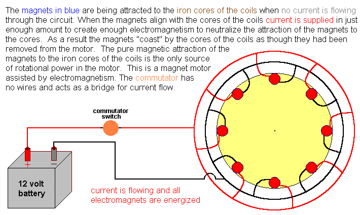
The theory is: The motor produces all power when there is no electricity and
when electricity is used it does no work of attracting or repelling the rotor.
The motor does require electricity to operate. This is explained in this
website.
This motor proved the principle to me. It developed 330 rpm but was not load tested for horsepower.
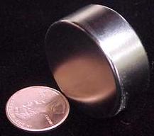
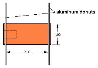
I then built a much larger/stronger motor using neodymium magnets 1.25" dia
by .5" thick purchased from Wondermagnet.
My first motor had complete negation of the attraction of the PMs to the
cores of the EMs with a close air gap. There was no surplus "repulsion" power
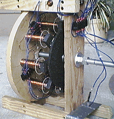
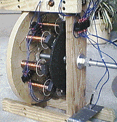
from the EMs. There were 8 EMs and 8 PMs. The new motor retains this
configuration.
On the new motor I had problems in the prototype. The first problem was back
attraction of the PMs to the EMs when they were energized to negate back
attraction. This back attraction reduced power output and efficiency.
Dynamometer tests confirmed 48% efficiency at 60 rpm. Motor size and bearings
also contributed to inefficiency and I'll address this later.
This is my original electromagnet core.
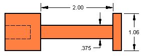
They were made from Carpenter 4% Silicon Magnetic Steel. This steel achieves
a high saturation level very quickly and retains no magnetism after the
magnetizing force is removed. It is what the "experts" suggested. I wound it
with 3 wires of 300' long 26 gage wire and energized it with 13 volts DC. The
air gap between the faces of the EMs and PMs was .040". This provided for a
combined attraction force of all the 8 PMs that was so strong I could hardly
displace the rotor from the EMs by hand with the motor at rest.
The backwards attraction of the PM towards the EM while the EM was energized
forced me to redesign the EM core. I used the same material with the dimensions
shown next.
I wrapped this core with 9 wires of 300' long 28 gage wire and energized it
with 13 volts DC. I got unexpected results. The repulsion electromagnetism
against the PM was great as the PM was slowly moved closer to the face of the
EM. But at about 1/4" air gap is where the "negation" effect of the EM on the PM
occurred. Any closer and the PM would overpower the EM and be attracted to
contact the EM.
At the 1/4" air gap if the PM were moved away from alignment relative to the
EM there was no backwards attraction force present, rather there was repulsion
force. The "backwards attraction of the PM towards the EM while energized"
problem was fixed but now I had the 1/4" air gap limitation which greatly
reduces PM to EM core attraction force.
I did calculations based on the original core which had 3 wires of 300' long
28 gage wire. If I replaced the 28 gage wire with 56 gage wire the
electromagnetic field increased by a factor of 18 times while the current draw
at 13 volts decreased 66%. I rewound the newest 1" diameter core with 36 gage
wire and made 7 more EMs and rebuilt the motor.
My crude winding machine would break the 56 gage magnet wire so I used 36
gage wire. It took 42 wires of 300' long 36 gage wire to wrap the new cores to
an overall diameter of 2.5".
Motor tests revealed that an 11/16" air gap produced the most power.
Dynamometer testing showed .5 ft/lbs of torque at 220 rpm, with an efficiency of
26%. Power and rpm had been gained over the first combination. Not very exciting
until you understand the inefficiencies of this huge motor design.
11/16" air gap provides for only a weak attraction force. The repulsion force
is good. So the current version of the motor is more of a repulsion motor than a
magnetic attraction motor. This is the point I'm at now.
This is a lot of "fat" to be trimmed off this motor.
I will build a bench test device to test various PM/EM combinations. PM
attractive forces can be measured at various distances and air gaps with this
device.
I probably need to reduce the EM core diameter and wrap it to maximum usable
amp/turns with the thinnest magnet wire to provide for the least power
consumption.
A point will be reached where EM core diameter, core length, winding, and PM
size yield optimum attraction force performance establishing the perfect EM/PM
combination.
Then I will experiment with EM/PM distances to determine the motor's radius.
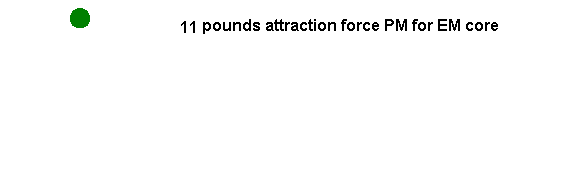
If I move a PM from it's center alignment with the EM the PM attractive force
for the EM core will decrease to an insignificant level. This distance will
establish the midway point of the PM between EMs. This graphic showes this
process. The PM is green and the EM core is blue.
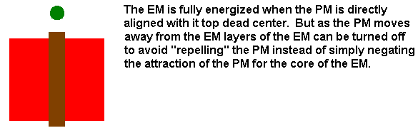
The EM strength needed when the PM is at a centerline alignment with it must
be reduced shortly after the PM passes so that the excess EM repulsion magnetism
doesn't repel the PM. I want the EM to be "invisible" to the PM when the EM is
energized. I don't want electricity doing work. The easiest way to decrease the
EM strength is to systematically turn off layers of winding starting from the
outermost winding and moving to the innermost. This will yield maximum energy
conservation. Several commutators are needed to accomplish this. The next
graphic illustrates this systematic de-energization.
I will continue adding information to the website as work progresses. Right
now I'm winding a new EM that has a 3/8" core diameter continuous to the end.
The length is 2". I will intentionally put more wire on it than I think is
necessary to achieve the strongest EM as possible. I will then take wires off,
reducing it's overall diameter, until the EM has only that amount of wire as
will add strength to the EM. Any wire that doesn't contribute to the strength of
the EM wastes current and allows the coil to heat up more than it should.
After it is tested I will take the wires off, reduce the length from 2" to
1", rewind it and test it. My goal is to have as little energy consumed by the
EM as is necessary. After I have my test data on the 3/8" cored EM I will build
other diameter cored EMs and test them until I find the perfect match of EM to
the 1.25" diameter neodymium magnets I have on hand now.
There are a number of other claimed overunity devices in operation today as well as proposed overunity devices. In no particular order here are the ones that impress me as having real industrial potential if they are truly overunity. As far as I know there are no proven overunity devices because if there were they would be on the commercial market and the owners would be billionaires. Please correct me if I'm wrong. Email Scott McGuire
Howard Johnson
Permanent Magnet Motor
I really like this invention. It requires no
external power supply and relies on continuing imbalance of interacting north
and south magnetic fields from the stator and rotor. Mr. Johnson believes he can
easily construct a 1KW generator powered with this magnet motor.
Bedini all
North Pole motor
This self-sustaining motor recharges the battery and
does work. Another builder has verified this to me. The rotor has 4 permanent
magnets and the stator 1 electromagnet wound with two different sized wires. As
a PM approaches the EM it induces a voltage into the smaller wire turns on a
transistor. Current then flows from the battery through the transistor to the
larger wire in the EM providing repulsion magnetism pushing the PM in the rotor.
As the PM leaves the EM the induced voltage to the smaller wire ceases, the
transistor closes and power is cut to the larger wire. My guess is that Bedini
is harnessing the CEMF from the collapsing motor drive electromagnetic field and
sends a voltage spike backwards to the battery interacting with the physics of
the battery and somehow recharging it. If this device can be replicated on a
large scale the implications would be huge.
More to come. I'm studying many more overunity devices and will post them
when ready.
electric car another article from Scott Mcguire
coildecreasing.gif firstmotoranimated.gif magnet46.jpg
mcmotor1.gif mcmotorcallaway.gif originalcore.jpg secondcore.jpg
spacinganimated.gif
