
USING SOLAR heat radiation ENERGY
By using some cardboard and some cheap al foil it is possible to capture the suns energy and use it to do some useful work.
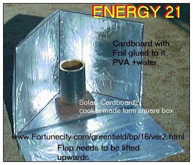
All that is needed is some pva craft glue ,a square cardboard box (tv box) and some cooking foil..
What you need to do is to remove the top flaps from the box and then cut the box from one corner to another so that what remains is a cardboard box with two sides and the bottom intact.
You need to fix to the inner box sheet of al foil so that the complete inside sections are covered with foil as shown in illustrations.
It may be easier to use ,if you flatten the cardboard so that you can place it on a flat surface.
To place the foil on the cardboard cover the entire inner surface with a mixture of 50 percent of water and pva glue throughly mixed together.
Place the foil on this surface ,
To do this neatly and so the foil adheres neatly, place one end on the cardboard and glue and pull into place rather than just placing all the foil on the cardboard at one and the trying to flatten it out.
When you have done this leave to dry it usually takes a couple of days.
You need also to make an adjustable reflector, that will fit corner to corner at the bottom of the box it make seem that you don't need it ,but there is a considerable amount of heat that is lost if it is not reflected back into cooking zone.
Some of these units I have seen will take about 1/2 hr to cook something in the middle of summer ,I doubt this would be practical in the middle of winter a good suuny day is what is really needed.
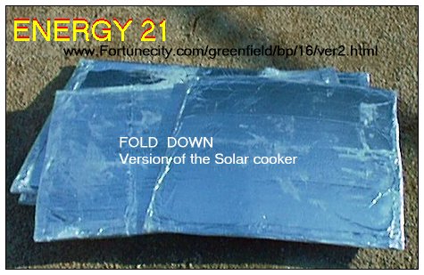
If you make a survival version as shown above you will be able to flatten the unit and take it camping with you.It no different to box angle version except the bottom two flaps are not joined together and you will need to mak a extra square section to place on the bottom.
If you get lost in the great outdoors they will make excellent signal mirrors as well.
Aim the box just slightly ahead of the suns path for best result.
It seems to work better if the cooking vessel is also black in colour.
Although not necessary if the unit not left in bad weather ,I have covered the outside cardboard surface with foil to offer some protection from rain.
Perhaps some adhesive plastic used to cover books could be used for the outer covering instead.
A METHOD TO PRODUCE CLEAN WATER.
A basic Solar desalinator.
I have constructed a desalination unit using the above method to run a solar desalinator.
I have built other units and some are on this web site but have not really been happy with the amount of water produced.
I believe this could be a better method.
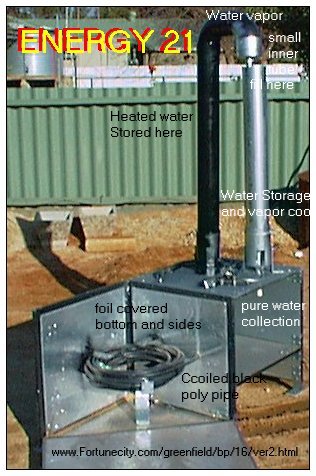
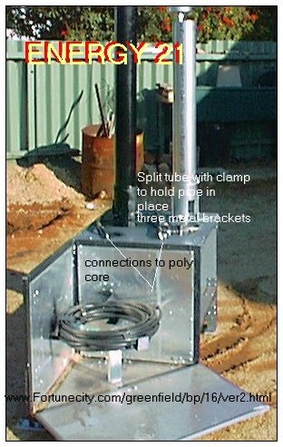
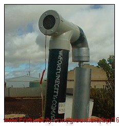
The Heating section is no longer made of cardboard but is made of wood and painted several times to offer some weather protection and plastic tape surrounds the edges of the wood and the inner sides are then covered with foil similar to the cooker above.
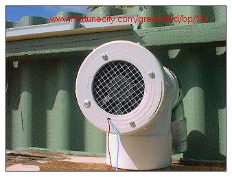
The rest is constructed using 6 inch PVC piping a couple of elbows and two end caps
A couple of six inch end caps
One end cap has two plastic screw thread fitting inserted into them and then fibre glassed to make a water tight search and is then connected to inlet and outlet of the hot water poly coil.
There also a small bass fitting that allows water to come in from the water storage tube.
The second endcap has two fittings screwd together and then also fibre glassed and then a length of one inch pipe is glued to it to make it water tight.
Another piece of pipe in inserted on the other of this join and this becomes pathway for the distilled water to the collector bottle.
And also a brass fitting is also inserted into the endcap that allows water from the coolant tube to flow toward the heating tube section.
The smaller pvc (1 inch )plastic pipe takes the water condensate and then drops towards the collector bottle below.
A couple of plastic taps and some small plastic elbows and a T sections you should be able to get this from your gardening irrigation supplier. (Basically all stuff come off the shelf and nothing is critical)
A roll of black poly pipe is then put in place in the heat zone of the unit and then heated by the sun.
Heated water is then allowed to flow so that the warmest water is found at the top of the black storage tube.
At this point the water is turned into a gas and pushed towards the condensation (silver) tube on the other side and then flows into the collection bottle below..
This part of the unit is filled water ,this section acts as both a water level storage section and at the same time acts as a coolant for water vapor as well.
Water is fed through a small flexible clear plastic tube about 1/4"D to the Black heating section 6" tube to replace that already processed and so that minimum of heated water is fed back to this cooler section.
The reason why the 6" heated tube section terminates in a smaller pipe after the 6" secpnd elbow , is that when a large amount of heated mass is fed through a small tube heat is lost and this should enable better water recovery production. (not yet proven)
To test this theory for yourself ,blow out of your mouth with you lips open onto your hand and you will feel that your breath is heated
Do this again but with your lips compressed and you will sense that this breath is cooler.
FILLING UNIT AND THE REASON FOR THE TAPS.
If I used no taps (valves) in this design, and tried to back fill the black poly hose, what would result would be an air blockage at the middle of the poly coil and no transfer of heated water would occur.
On filling the unit ,the tap (valve) nearest to heated water storage section is closed , and the bleed tap turned to the open position until all air air has been purged out when filling the complete unit..
The bleed off tap is then closed and the alternative tap(valve) is opened and the filling returned water is allowed to flow to hot war storage section and thus completing the loop.
By the way
When water has been heated the bleed off tap(valve) could also be used to collect hot water from the unit for other uses..
The unit could ideally be made from metal but I believe the heating section should be insulated so that heat is prevented from leaving the main heating area around the poly pipe coil..
SOME COMMENTS
The condensation idea of this device has not been tested yet due to our area now in winter but will be once the weather warms.
The the heating section idea has been tested and has vapourized a complete 5 kilogram can of water in one week usng the cardboard models as shown on this web page.
The poly coil of plastic piping will indeed heat up and water in it has reached a scorching temperature.
Because plastic pipe tends to kink (buckel)when heat ( solar included ) is applied I would recomment that no bends are made with the poly pipe and where a bend is required use a elbow section instead.
Everthing that holds hot water has been painted black to ensure maximum solar heat capture and in the cooler area everthing is planted a silver colour to help lower the temperature difference between the two sections namely the heating and the cooler 6'' pipe section.
The unit here is really only a demonstration of the concept.
I believe this idea could be upsized to produce more clean water and the two sections could be separated to where the heating section could be outside in maximum heat exposure area and the cooling unit placed in shaded or underground area and all powered from the sun.
Finally:
At this stage I am hopeful that this unit will be in the gadgets section of the South Australian Riverland Field day working this year of September 2004 and at the Loxton show of October 2004
so if your there come over and have a chat
Geoff
