I was thinking of how to use a doughnut magnet and coil of wire to make a generator that was simple and easy to construct and this idea occurred to me..
 <\A>
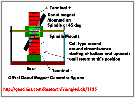
<\A> The doughnut magnet can be scavenged from the type sold as a welding aid and can be removed from the metal plates covering the magnet by simply drilling the rivets holding it together and then simply removing the enclosed ceramic magnet. The one I had in mind can be obtained for about seven to eight dollars.
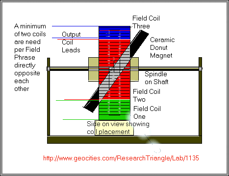
If the doughnut magnet was to be mounted in a straight up that is at ninety degree to the axle I believe result power output would be very small due most likely to the less that exact mounting and spinning vibration but however an interesting result may be result, if the magnet is mounted on spindle as illustrated in the diagrams on this page.
Of course power output would be dependent on the magnetic strength of the ceramic magnet and the composition of the copper winding that would be mounted on the diameter surrounding the rotating magnet as illustrated on my diagrams and the speed of the rotating ceramic magnet and the distance between these two components with the minimum distance being the better to strive for.
With the angle of the magnet as shown,and being rotated by some means (water air or some other means ) there would alway be a changing magnet field in relation to the coil winding, because of the rotation of the permanent magnet
There would also be a variation of field strength in a any given location with the maximum being directly opposite the closest position to magnet.
Just imagining this generator I see it as a DC generator with no commuters and brushes to cause power losses or to wear out.
As I have not yet constructed the generator I am unsure which is the best type of winding to use
I have shown in my diagrams two types
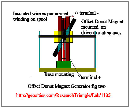
(A) One that is wound around a circumference starting a given location and gradually wound upwards and then back to beginning and so on.
One option to think about here would be to make a series of coils connected through diodes as per the three phase article.
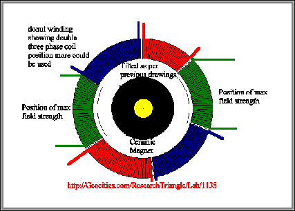
If each coil is wound as to be a width of no greater that the thickness of the strongest field position of the said ceramic ( if you look at the drawing at bottom of this page, the central grey area of the magnet should give you some idea of what I mean ) The output leads should be connected as per normal phase connection (DELTA OR STAR increased from three phase to as many as is needed to match the number required to match the circumference of diameter in the metal circle sourounding the rotating magnet.
(B) However I believe a better type would be a winding similar to what you find on a spool That is a round and around the circumference, This magnetic effect reminds me of a long garden hose gradually being squeezed from end forcing water out at the other end something like blood pumps in hospitals
Whilst both types of coils could be wound on non metal formers but I believe using a magnetic metal in it would be of an advantage.
I believe this device may have similarities to the electric dynamo as used on bicycles but think the idea of using an offset magnet on a rotating axel is something new.
If you have any ideas in relation to this generation please let me know I would be interested in hearing your comments
Some notes on three phase power generation
Geoff