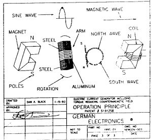
ELECTRIC CURRENT GENERATOR INCLUDING TORQUE REDUCING COUNTERMAGNETIC FIELD.
I have other devices on my web site along the lines here, but this one is interesting on several
grounds in that the author mentions the fact the device needs to be in harmony to function.
The device has actually been built and in common with one other device I am aware of ,which decreases the input power when under a Load.
The author also has made a video of the device in action some parts of which you can download from the slection below .
( if you don't havethe RealPlayer 5.0, you may download it freely at :http://www.real.com/products/player/)
The author also suggest put several in combination to decrease input even more.
For further info suggest you contact the author at the email address below or the postal address supplied below.
An Article supplied to this web site by
Box 2091A
Shepherd Tx 77371-9222
U.S.A
Describing his invention.
In the "lenz- test, the core of the coil is not shown, explained, or for that matter even seen as an inductor, much less, one that can be "tuned"
Standing waves will be generated with this arrangement, being a standing wave a pole of opposition will be generated.
These are the conditions the "lenz" test were done.The pole generated at the ends of ll will always oppose the motion, if ll is formed as part of a complete tuned circuit, meaning providing a load for ll, generation of a pole
that will enforce the motion can be generate.
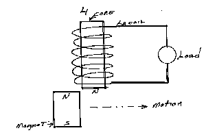
To understand this correctly,the core and the coil should be designated as l1,l2, with this in mind,if a tuned
circuit were formed,the load would be l3
LENZ'S LAW
The direction of an induced e.m.f. is such that it opposes the chance that produces it. for example, if a
permanent bar magnet is moved towards a coil that forms part of a complete circuit, then current flows so that
the magnetic field abound the coil repels the magnet, if this were not the case, no work would need to be done
to cause charge to flow, breaking the principle of constant energy"
(LAWS OF CONSERVATION OF ENERGY)
this is absolute wash.
If a current is made to flow in a coil that is a complete circuit, 1 of 2 possible poles will be formed. These poles have nothing whatsoever to do with the "constant energy law",
But rather simply a current causing an electromagnetic field to be formed that must dissipate. If you are moving a magnet towards or away from a coil wound on an iron core, but not part of a tuned circuit, a standing wave will
be generated and the pole created will oppose the direction of motion.
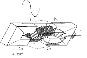
On the other hand, if a coil is wound on a core that is a part of a tuned circuit. see diagram
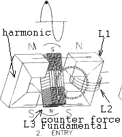
If we remove the aluminum from the center part of l-3 and replace it with a nonconductor, it can be seen that a complete circuit for the counter force is not present. This will cause dissipation of the counter force on first
entry of l-3. (steel ends) and not as an inductive load,resulting in the formation of poles that,will oppose the direction of motion.
see diagram below.
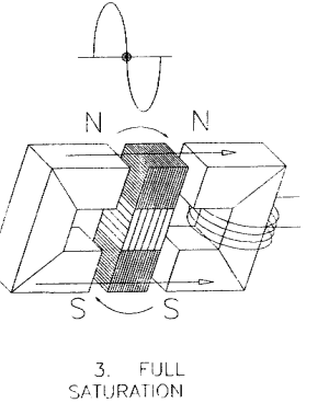
It can also be seen that if the circuit in the l-3,inductive load is not complete as a whole unit,generation of a harmonic can not occur, and with out this you can not shift poles.
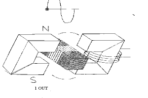
l-1 being the core, l-2 being the coil (e.m.f. out) l-3 being rotary "tuned load" (l/2 length of l-2) the resulting electromagnetic field will be obsorbed by l-3. upon being obsobbed, the generation of a hormonic will occur as well as a change of direction of the current. (180 degree phase shift)formation of the magnetic poles will occur on the harmonic.
If we remove the aluminum from the center part of l-3 and replace it with a nonconductor, it can be seen that a complete circuit for the counter force is not present. This will cause dissipation of the counter force on first
entry of l-3. (steel ends) and not as an inductive load,resulting in the formation of poles that,will oppose the direction of motion.
see diagram below.
It can also be seen that if the circuit in the l-3,inductive load is not complete as a whole unit,generation of a harmonic can not occur, and with out this you can not shift poles.
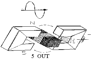
for those skilled in the art of transmitter final circuits (xmtr tank circuits) the diagram 1a below may lend some
help in under standing the basic principal of operation of the generator.
diagram 1a below has been drawn to show the "l coil" or inductors so they may be compared to that of a transmitter final circuit.
If you remove l3 and the magnet from the diagram, or cover the two with a piece of paper, and show the top end of ll connected to an antenna, and connect bottom end of ll to earth ground.
It can clearly be seen that this is a basic transmitter tank circuit. putting l3 and the magnet back
in to place, and now rotating l3 through the space provided between the magnet and ll, ll being made of steel, induction will occur in l2 upon rotation of l3, and if a load is placed on l2 a counter magnetic force will be generated. with l3 being at the right place at the right time and of proper length. (aprox. 1/2 the length of ll)
l3 will act as a proper load for the c.f.
As the counter force is being dissapated a harmonic is being generated that must dissapate. l3 not having an inductive path will form a standing wave at the ends of l3.
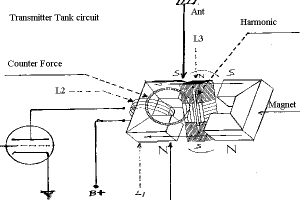
This standing wave will cause the poles at each end
to be created. the poles created will add to the torque causing the motion of l3.
>>>>>
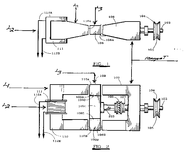
The following are pages from U.S. patent # 5,191,258
You may care to use the patent searcher to view the rest of patent
using the the patent server as my web site listings. webmaster >>
It is important at this time I make mention that the "l" designations ll-l2 and l3 are not shown on the drawing but have been added at this time to show there functions as a tuned circuit.
it is also important that i say that the U.S. patent rules would not let me show the "L" designations or make mention or reference to them as the patent process was two far along, or to put it another way, I did not enter
them on the first application, and as such could not enter them at all.
thanks from Jim German
United States Patent [19]
[541 ELECTRIC CURRENT GENER.ATOR INCLUDING TORQUE REDUCING COUNTER
MAGNETIC FIELD
[76] Inventor: James W. German, Rte. 2, Box
2091A, Shepherd, Tex. 77371
[21] Appl. No.: 757,548
[22] Filed: Sep. 11, 1991
151] Int. CI.5 H02K 1/12
[521 U.S. Cl 310/254;310/46;
310/168;322/49
[58] Field of Search 310/254,113,102 R, 310/46, 90, 156, 192, 264, 67 A, 138, 166, 153, 168; 322/46, 49, 50, 51, 52, 47
[561 References Cited
U.S. PATENT DOCUMENTS
2,218,859 10/1940 Schweitzer 322/46 X
3,261,998 7/1966 Bosco, Jr. et al 310/268 X
3,431,444 3/1969 Wilson 310/168
U5005191258A (barcode number )
[11l Patent Number: 5,191,258
[45] Date of Patent: Mar. 2, 1993
3.983,430 9/1976 Howard 310/168 X
4,027,229 5/1977 Frink 322/50
4,237,391 12/1980 Schur et al 322/49 X
4.385.246 5/1983 Schur et al 322/49 X
5.030,867 7/1991 Yamada et al 310/156
Primary Examiner-Steven L. Stephan
Assistant Examiner-E.H.To
Attorney, Agent, or Firm-Jackson & Walker
[571 ABSTRACT
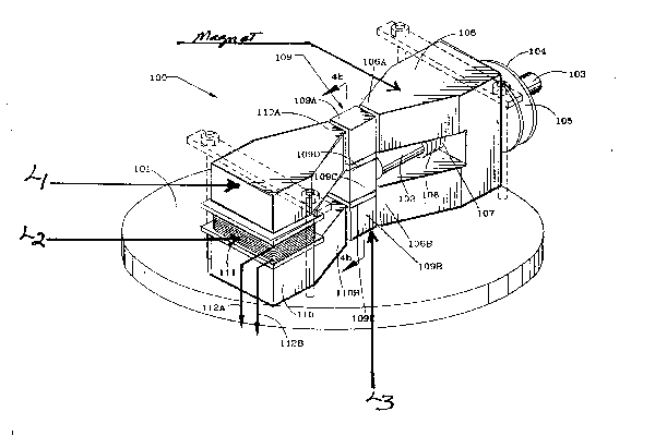
An alternating electric current generator comprises an armature rotatably carried by a
drive shaft and positioned between stabilized. non-moving magnetic elements. The end
armature has first and second magnetic field transmitting sections with a magnetized
section sandwiched there between. As electric load is applied to the generator, a countermagnetic
field is generated through the armature to increase speed of the drive
shaft and thereby lessen torque required to rotate the drive shaft.
1 Claim, 3 Drawing Sheets
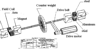
Some drawings Illustrating the device in various positions
( if you don't havethe RealPlayer 5.0, you may download it freely at :http://www.real.com/products/player/)