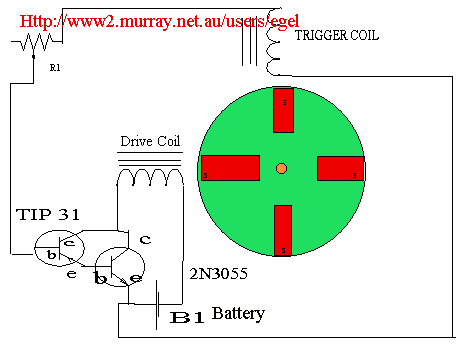
Below is a circuit diagram an Adams or Lenzs Motor that a correspondent has sent to Solaris. and some of the letter is reproduced below.

This means it will get very large and heavy and may reach 95% efficiency.
The reason being ,coils cab be so connected as to reduce DC resistance to almost zero resistance. it the nature of things.
The bad thing it produces little power for its weight,and the only advantage is you can build it.
Its very expensive for the power it produces.
One retired science teacher of 89 years old told me the Adams machine is just a copy of machine built by scientist Lenz, to prove that no motor or generator can be overunity.
He claims that he played with design as boy. Another correspondent sent me a primate picture of it dating back to 1820.
Its a very educational device built to demonstrate that overunity does not exists.
The simple circuit above are great for the Adam/Lenz motor.Its best to use a larger 8 magnet rotor with four drive coils,but two drive coils works fairly well. Expect 15 to 27% efficiency dependiing on skills at building.
The transistors are available at Radio Shack and so are the magnets and it takes about 6 ceramics to make one magnet. I use the 1/ 1/8" diameter magnets.
End of article.

A while ago there appear on the market a device called a Levitron which seem to be doing something
interesting.
The advertising suggest it was possible to have a object spinning in mid air.
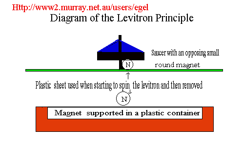
After examining the device it seems to be two magnets in an replusive mode as the diagram ilustrates.
The Trick it seems is to place a plastic or non metallic board over the bigger bottom magnet and then on the board place the saucer shaped levitation device and then try to spin the device at a speed that will
cancel out the desire for the magnet in upper device to flip over and be attracted to the bottom magnet
When this is achieved the plastic board is removed and it the saucer hangs in mid air.
The Levitron seems to have a weight in it also maybe this is part of the effect needed also.
By doing this the magnets remains in an opposing mode and seems to remain there suspended there spinning.
When the spinning speed decreases to a level where this is not possible the levitation ceases..
Demonstration of a home made levitron
Another demonstration of the levitron
From: Willy-André Daniel
Subject: About the Levitron
I've read a bit about the Levitron after I bought one, and I think I'm
able to convey a few details that you seem a little unsure of.
(actually, I stumbled across your page looking for information in my
attempt at building a "perpetuator" for my Phenominator, which is the
same thing as the "Levitron Deluxe Platinum Edition".)
The spinning top consists of a ring-shaped non-metallic magnet
(neodymium?) with a plastic axle, and weights (brass and plastic shims
in different sizes, and a rubber O-ring to secure the shims to the axle)
to balance the top with an accuracy of 0.1g.
The funny thing is: A similar device has been invented, but not
patented, which does away with the weights altogether. Instead, the base
is adjustable. Unfortunately, this device isn't being manufactured.
How can you adjust the base, since it's one big magnet? Well, it doesn't
have to be, and in that unit, it isn't. The base magnet in a
Levitron-like unit can be one magnet shaped like a dish, one magnet with
a hole in the middle, or several magnets. Several magnets can be
arranged in two ways: Either a large magnet with a hole in the middle
and an opposing magnet in said hole (Like, I suspect, my Phenominator)
or a polygon of magnets, with or without an opposing magnet in the
middle. The original patent for this magnetic levitation principle
mentions just such an arrangement. That is, not the Hones & al. patent
that's printed on the Levitron, but the original patent. (Which Hones
apparently stole, btw. The real inventor never got a penny from the
Levitron sales as far as I know...) Anyway, such an arrangemant CAN be
adjusted! My guess is that the adjustable base contains three or more
magnets, the distance between which can be adjusted. With a really light
top, I think this can be cool: Lighter top -> greater distance between
magnets -> much larger "bobbing" motion by the top.
If the Levitron simply used two opposing magnets, and they didn't have a
special shape, the top would slide sideways out of the base's magnetic
field. The reason it doesn't, is that both the base and the top projects
roughtly toroid-shaped fields of different sizes, such that one fits
"inside" and on top of the other. I thought gyroscopic forces was what
prevented the top from overturning, but I must have been wrong. If I had
been right, the top would be increasingly stable with increasing spin.
It isn't! It's stable between 18-38 rps approx. Outside of this
envelope, it's inherently unstable. Go figure.
Of particular interest (probably to you as well) is the functional
principle of the perpetuator. According to Hones' patent, it seems it's
simply a coil on a soft iron plate former, placed horizontally
underneath the Levitron base, which is energized with a short pulse
approx. 30 times/s. Dead simple. He states that the top itself spins
1.25-1.5 revolutions/pulse. Hey, the only thing missing to make a really
cool display stand is syncronized stroboscope lighting to "stop" the
spin.
Hmmm... I just started wondering if it would be possible to make a
self-adjusting base to compensate for temperature changes and soforth.
Could make it possible to suspend a top indefinately in combination with
a perpetuator...
I'll have to contemplate that for a while...
I hope some of this information was of interest to you. If you would
like some more detailed information, e.g. names, the actual patent
numbers, URLs to the patent documents or URLs to more information, just
email me.
Best regards,
Willy-André Daniel
It seems to me some of the above idea could be incorpated in a
spinner or gyroscope.
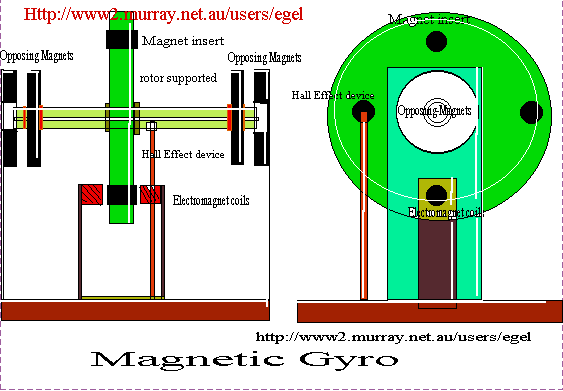
The diagram shows an axel on to which a flywheel is mounted
onto to which are imbedded an even number of magnets and in
a position where they are properly balanced.
At each end of each axle are mounted and fixed into position
two circular magnets at each end (Radio Shack) and placed into
the center of the opposing magnets on the two support pillars.
The flywheel is driven by a pulsed electromagnet triggered by
a Hall field Effect device driven by a P/magnet on the flywheel in a
different position.
Please note the device is not drawn to scale and may be bigger
if the proper magnets can be found.
At first the rotor assembly will rest on magnets on the support
pillars but as speed builds the device should
center itself and rest on a cushion of magnetic fields and should
allow some interesting gyroscopic experiments..
If you build such a device let ke know how you get on.
Computer & software engineer
The Magnetic Gyro

