Here below are the details of a very interesting water pump used in the earlier history of and a part of Riverland irrigatrion area. The pump no longer provides this service as modern electrical equipment performs this. However the operation is interesting and may give some an insight in to making something better. The pump can be still seen in operation on Sundays most South Australia Public long weekend holidays.
The Humphrey Pump, was invented by Mr. H.A. Humphrey, eminent Gas Engineer and Chemist. Born in London in 1868 and educated at Finsbury Technical College and the Central Institution of the City Guilds, Kensington, England, he died in 1951 at Cape Province, South Africa.
His pump is an internal combustion pump in which the force exerted by the explosion of a mixture of flammable gas and air acts directly on the surface of the water, forcing it to an elevated position.
The aim of Mr. Humphrey was "to produce a pump of great simplicity and strength of construction in which the explosive force is exerted directly on the water and in which no rotating flywheel, solid piston, rotating crank, connecting rod, bearings or glands of any sort are required".
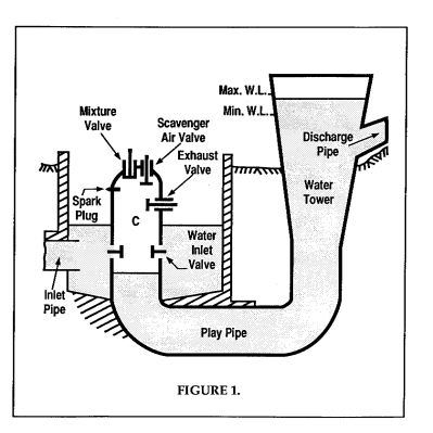
The diagram in Figure 1 shows the essential components of the pump, and is similar to an experimental pump designed by Humphrey, which worked satisfactorily from the first occasion on which is was started.
The pump was composed of 3 main parts, viz:-
1. The combustion chamber C, fitted with an exhaust valve, gas and air mixture valve, scavenge air valve and spark plug.
2. The water suction chamber, and valves.
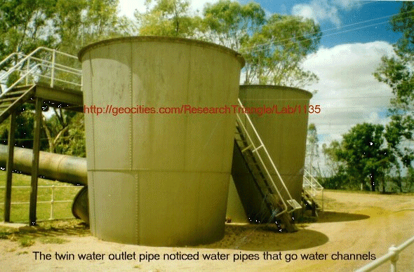
3. The playpipe, connecting to an elevated tank and outlet pipe.
It will be noted that the form of the pump, is that of a large U-pipe closed at one end and without any obstruction to the free flow and oscillation of the water column within the pipe. The only moving fittings in the pump are the various valves and an interlocking mechanism to automatically lock or unlock them according to their requirements in the cycle of operating events. The interlocking and ignition apparatus are operated by the pressures within the combustion head, to which they are connected. It was from this basic design that subsequent models were developed for the London Water Supply Authority at Chingford, installed in 1913 and the Cobdogla Pumps which are practically replicas of these pumps, apart from their output capacities.

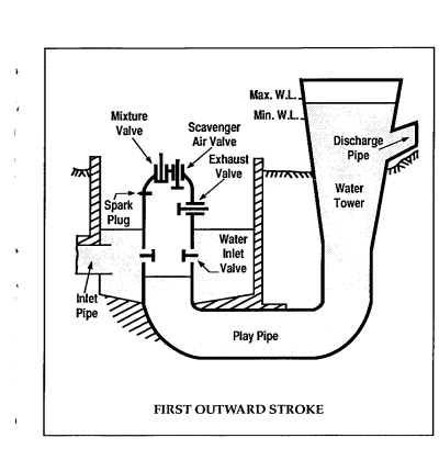
FIRST OUTWARD STROKE The pressure on the water exerted by the force of the explosion and expansion of heated gasses, sets the water column in motion with increasing velocity. The Kinetic Energy acquired by the rapidly moving column of water, causes it to flow outwards until a partial vacuum is formed at the combustion end of the playpipe. When the pressure falls to nearly that of the atmosphere the exhaust valves open inwardly with the assistance of springs. The lightly spring loaded water inlet valves open inwards admitting a large quantity of new water into the playpipe, partly to follow the column of outgoing moving water and partly to endeavour to fill the pipe to the same level as the water in the suction sump.
With a further fall in pressure, the scavenge air valves, also lightly spring loaded, open, allowing pure air to be admitted to occupy the space above the exhaust valve level, a retentive valve in the exhaust valve casing preventing the return of burnt gases from the exhaust pipe. By means of an interlocking apparatus operated by pressures within the combustion head, the exhaust and scavenge air valves were released when the explosion occurred and the gas mixture valves were locked in the closed position. A portion of the outgoing water column spills out into the receiving basin, starting a syphoning action in the outlet discharge pipe.
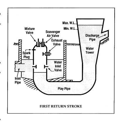
FIRST RETURN STROKE The momentum of the water column expends itself at the end of the first outward stroke, allowing the water column to flow back by gravitational force towards the combustion head. This in turn drives the burnt products of 'combustion through the open exhaust valves, ultimately closing them by impact of the water. The spring loaded water inlet and scavenge air valves were closed when the pressure again rose to approximately that of the atmosphere. The returning water column, having gained considerable velocity, now compresses the scavenge air (mixed with a percentage of spent gasses) in the top of the combustion chamber, forming a compressed elastic cushion.
The energy thus stored in this cushion is then equal to the energy given out by the rapidly moving water column, urged on by the static head behind it, so that the cushion pressure is considerably in excess of that due to the static head. The interlocking mechanism, now operated by the cushion pressure, automatically releases the catch from the mixture valves and locks the exhaust and scavenge air valves.
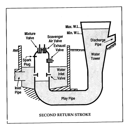
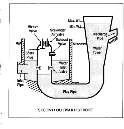
SECOND OUTWARD STROKE The expansion of the compressed air cushion now drives the water column outward again, the pressure becoming atmospheric as the surface reaches the exhaust valve level, and if it were not for the friction losses in the playpipe it would ultimately be driven out to the same position that it occupied prior to the commencement of the first return stroke.
The outward movement of the water column continues until a partial vacuum is again formed and the water inlet valves open, admitting a large quantity of water into the playpipe.A portion of the water column at the outward end again overflows into the receiving basin.
The gas mixture valves alone being free to operate, a new charge of inflammable gas and a small amount of air is admitted into the combustion chamber, which mingling with the scavenge air taken in on the previous stroke, forms a fresh combustion mix.
SECOND RETURN STROKE The second outgoing impetus given to the water column having expended itself, a return flow again takes place, and, all valves being closed, the new charge is compressed and fired automatically at the moment of maximum compression. The electric current to the coils is switched on by a plunger-operated ignition mechanism.
Thus another cycle commences, and providing that the correct mixture of air and gas is admitted by the proper functioning of valves and the correct timing of ignition gear, the four cycles continue with a regular pendulum action of the water column, although the length of the strokes are unequal. A portion of the water column is discharged into the receiving basin on each outward stroke.
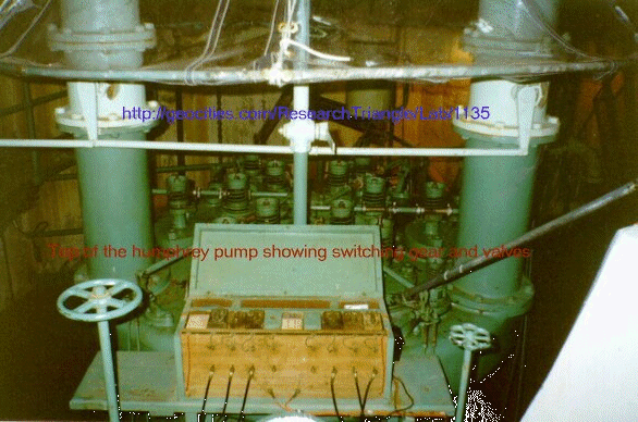
The design of the Cobdogla Pumps differs from the original experimental model, in that multiple valves and spark plugs are installed in place of the single fittings in the original, the combustion head is dome shaped and the delivery tank is replaced by an inverted conical tower from which the water is syphoned to the receiving basin. The operation however does no differ in any respect from that of the original design. The multiple valves open and close as one, and the multiple spark plugs ensure a complete and sudden detonation of the entire explosion charge.
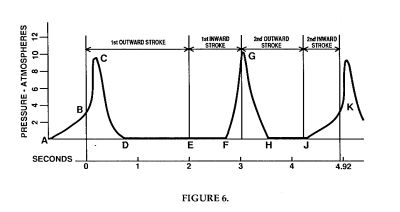
A typical indicator diagram is shown in Figure 6 on a time basis. AB is the period of compression of the combustible charge which is fired at B causing a pressure rise to C. CD is the expansion curve during which work is expended on the water column. The end of the stroke is E, scavenger air and new water to take the place of that discharged during the previous cycle, being admitted between D & E. At F the exhaust valves close and the cushion reaches a maximum pressure at C.
The second outward stroke then commences, the gas charge being taken in between H & J where the second return begins to compress the new mixture, the explosion again taking place at point K, to start a new cycle of events.
The gas for the Cobdogla Pumps was originally supplied by two updraft producers with scrubbing and tar extracting plant and the fuel used being mallee, box and redgum wood, which was supplied from the extensive wood stacks situated to the North in 6 ft lengths.
The wood was cut on site into 2 ft lengths for feeding into the producers. The May Bros. saw bench used in this operation is part of the machinery display.
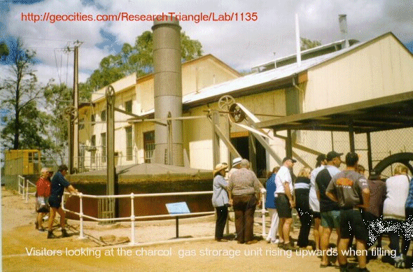
The installation was designed by Mr. W.F. Saunders A.M.I.E. Australia and was manufactured by Messrs. May Bros of Gawler, and erected by the Irrigation Department. It produced 26,500 cubic feet of gas per hour to a gasometer of 2,2900 c. ft. capacity. The power to operate the various auxiliary plant for the pumps saw bench and gas plant was supplied by a 30 hp Crossley Gas Engine. This engine is still in situ and in working condition, but all auxiliary plant is now electrified.
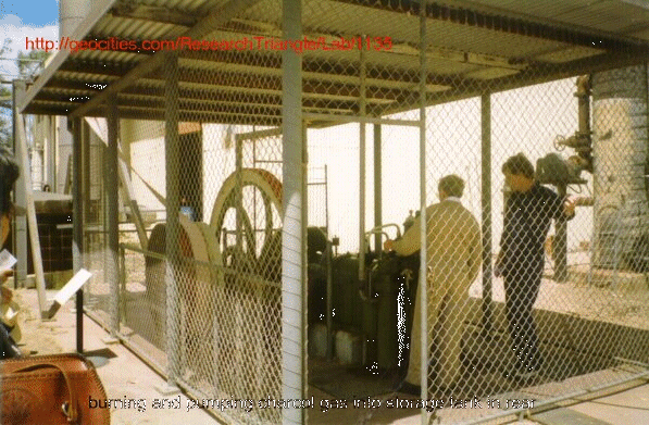
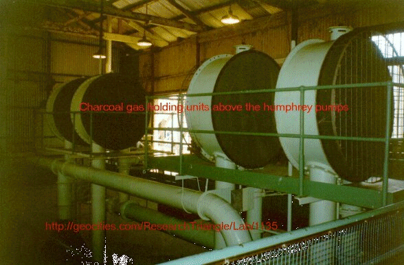
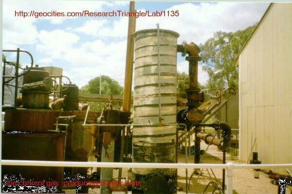
At the closing down of the Humphrey Pumps from service in 1965, the producers were in poor condition and were scrapped. Consequently, when one of the pumps was to be restored, investigation was conducted to find a suitable fuel. Bottled gas was found to be too expensive and a suitable gas producing plant was located at Murtoa in Victoria and purchased and installed at Cobdogla in 1985. This plant is fuelled by charcoal and supplies sufficient gas to operate the Humphrey Pump for the short periods required. The plant is currently being refurbished, as funds allow.
Investigations revealed that the tar had considerable calorific value if reburned in the producers, but because of the significant cost, the tar was piped to the North of the plant and discharged into a backwater of the river.
This large black, malodorous lake, adjacent to the new highway within a few hundred metres of the town was a permanent reminder to residents and travellers of the presence of the Humphrey Pumps! It was finally rerouted to a receiving basin close to the pumps, where the solidified tar is still visible. It is pleasing to report that within the last 30 years, nature has erased all trace of the original tar lake.
THE COBDOGLA PUMPS The Humphrey Pump appeared to fulfill the requirements of the main pumping station of the proposed Cobdogla Irrigation Area of over 10,000 Acres, as it was a high volume and relatively low lift pump of higher efficiency than a conventional steam plant.
Officers of the Irrigation Department made an inspection of the Humphrey Pumps installed at Chingford. Impressed with their ease of operation, reliability and low cost of maintenance, the decision was made to install 2 of the Pumps in preference to a steam driven plant.
They became the only pumps of their type in the Southern Hemisphere, from a total of only,12 manufactured world wide. During the reconstruction period it was decided by the Department to raise the level of water in the suction sump by 6 ft. to take advantage of the increased pool level of the river. This was caused by the installation of LOCK 3 near Overland Corner, which had been put in hand after the installation of the Humphrey pumps was started.
The pumping head was thus reduced from 34 feet to 27 feet. This had the effect of reducing the working horsepower and hence the fuel consumption, but due to the unique design of the Humphrey Pump, the overall efficiency was slightly reduced. With the effect of reducing the head, the length of the water in the playpipe was increased, thereby increasing the time period of the cycle and hence the number of delivery strokes per minute.
To have achieved the highest possible efficiency it would have been necessary to reconstruct the pumps to shorten the playpipes, but this was not a practical proposition.
The guaranteed design output was eventually achieved by further modification to the valve action, allowing a greater volume of gas~air mixture to be admitted to the combustion head.
After many years of trouble free operation, the Humphrey Pumps were finally shut down in 1965 due to diminishing supplies of wood fuel. They were replaced by an electrically powered pumping station constructed next to the Humphrey Pumps.
The Humphrey Pumps were completely submerged in the record flood of 1956, and were returned to active service when the waters receded.
All pumping for the area now is carried out by an electric pumping station situated on the main stream of the river, which replaces the Cobdogla and Loveday Pumps.
ACKNOWLEDGEMENTS Much of the information is taken from a paper by Mr. J.1. McLauchlan, an associate member of the Institute of Engineers, and presented to the Adelaide Division in Adelaide, March 1932. and taken from a booklet from The Cobdogla Steam Friends Society Inc.
P.O box 208 Berri S.A phone 08 8582 2603 The Barmera National Trust P.O box 472 Bamera S.A. 5345 Phone 08 8588 2521


