
My efforts to create a high voltage generator or a possible FE/device
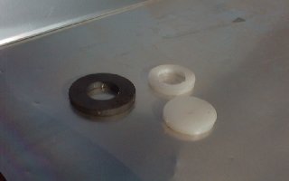
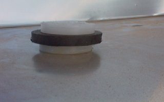
It is mostly made from persplex (clear plastic ) made from round pieces as shown below in photos which can be cut using a simple hand drill attachment with several cutting edges to give different diameters and then glued together.
All small magnets shown here consists of two pairs together although one of them may be hidden sight
All magnets on opposing surfaces will be opposition to one another .
The small magnets are one inch magnets as supplied by Radio Shack or Tandy Electronics.
The larger magnets are from magnet welding aids which I have dismantled to leave the magnets free.
It will consist of a twin rotating disks when completed and motivated by a pulsating dc current and activated by a sensor coil mounted next to the opposite bar magnet position.
It will have several things in common with Wimshurst Electrostatic generator as described elsewhere at this site and to the Swiss ML machine as from the front page of this web site.
It is hoped that the three pairs of rotating opposing magnetic fields in the device may create scarlar fields that will aid in addition collection of useable energy.(this is yet to be seen however)
The magnets are arranged with the same poles facing outwards similar to ideas by Robert Adams but where his has six magnets mine has only two bar magnets.
You may care to look at other parts of my web site to give you some idea what I attempting to do with device.
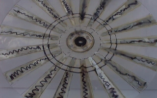
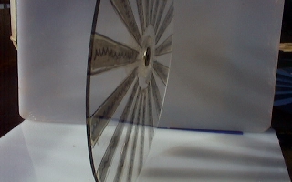
The above is a rear view of (one of the two round disks> each approx 16 inches in diameter with metal segments at 20 degrees each segments covering a 20 degree radius making 18 segments in all,notice too the magnet mounted in the center .There is also a hole drilled to the inner diameter of magnet center though plastic disk to allow the insertion of a shaft later on. There is a small ring cut in center of the larger disks to allow 1" magnets to just slip into it.
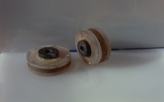
When the twin magnets are placed in the center they should only be just a bit thicker than the thickness of large ring itself. The large disks are approximately 3cm in thickness.
When the two disks are placed back to back the two sets of magnets will oppose one another and be held apart by magnetic repulsion.
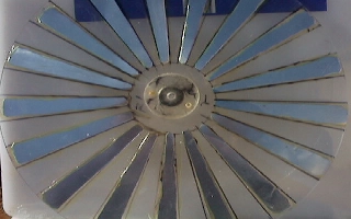
The same disk as viewed from the front notice the smaller flat persplex ring holding magnet in place. All parts are glued and held together using a good contact adhesive and then allowed to set for a couple of weeks or so.
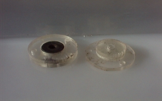
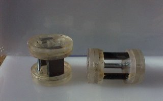
The opposing bar magnets and then are covered with further plastic rings with holes drilled to accomadate the nuts at each end. (one of two units are needed)
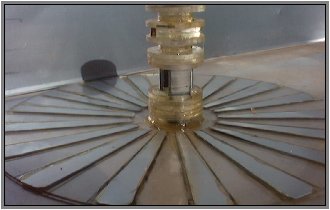
View showing disk and drive unit glued in place not shown here is the double magnet in center of the top as is common to other parts.
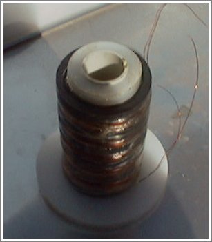
View from the top showing similar coils wound around the magnet stack and held in placed at the moment by cheap sticky tape.
As I haven't decided yet but I may place a coil similar to the hooper coil idea in the center tube or I may place a capacitors here connected to one the bifilar coils.
I may also add a step down transformer winding coil instead in the center similar to the automotive coil this will be determined by experimentation.
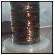
Close up of one of the twin coils wound around the plastic spacers and between the spaces left by magnets. The windings are wound at the same time in the same direction in a idea introduced by Tesla to reduce capacitance.
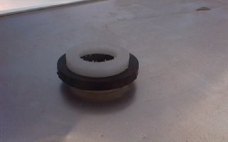
View from top showing the center holes in plastic spacers.
view showing how magnets are separated by plastic spacers these are then glued to magnets and held in correct alignment not show here.
Complete Plans will available for sale when device is completed sometime in the future if working of course or reults prove interesting.


