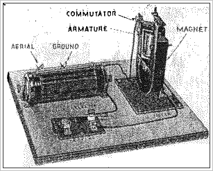

This novel radio operated device shown for the first time at the New York Radio Show is easily constructed. Nathan I. Hall from Radio Craft page 464 Feb 1936
An electric motor can be built using materials usually found in the radio facts junk box which will run on radio power received from stations some miles away.
The construction of the motor is not at all difficult and the average radio fan will find it both an interesting and instructive diversion from his usual radio activities.
(This "motor", essentially, is a galvanometer provided with bearings and a commutator that allows continuous rotation in one direction. Editor )
As might be expected, such a motor cannot be used to drive any mechanism as all of the power developed is used In overcoming friction in the motor itself.
The motor built by the writer will run on all input of one ten millionth of a watt armature current 7 microamperes and armature resistance of 2000 ohms and call be truthfully called a "flea-power motor."
The major parts necessary for its construction are: a crystal receiver, a horseshoe magnet, a short piece of iron rod and some small enamelled wire from an A.F. transformer secondary or a ford coil secondary.
As this motor operates oil D.C. only, the purpose of the crystal receiver is to tune in the desired station and to change R.F. current induced in the antenna into D.C.
A signal loud enough to be easily heard will be sufficient to operate the motor.
It is necessary that the current through the armature winding be reversed at the end of each half revolution of the motor.
On weak signals this must be done with a hand switch but on powerful signals it may be accomplished with a mercury or metal segmented commutator.

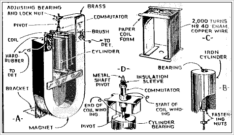
Figure 1A shows the top and side views of the motor. The dimensions of the various parts are not at all critical and will be determined by the size of the permanent magnet available.
The iron core for the rotor consists of a Piece of iron rod mounted between the magnet Poles. The diameter of this iron cylinder should be from ½ to 5/8 inches. less than the distance between the magnet poles. (A good length for it is half the length of the magnet).

Contrary to the usual motor, this core does not rotate but is fixed and the winding rotates around it. (See Fig. 1B) The only part of the motor where special care must be taken is in the construction of the rotor coil form.
A good design for this form is shown in Fig. 1C. It is made of stiff. light cardboard or fibre and care must be taken to see that it is symmetrical. The coil form should clear the iron care by about 1/16 in. on all sides. It will be seen in
Fig. 1A that the core is held in place by a pivot which must pass through the bottom of the form. The hole through which this pivot passes should be approximately twice the diameter of the rod. To the top of the coil form is glued a short length of hard-rubber rod.
This rod supports a phonograph needle which serves as the motor shaft. The needle protrudes through the coil form and its point rests in a centre punch mark in the top of the iron cylinder. The top of the hard-rubber rod is hollowed out slightly so that it will hold a few drops of mercury, or it is pivoted at the top with a second phonograph needle as shown in the details of Fig. 1. The last step in the construction is the winding of the rotor. The more wire used. the better will be the results.
The writer used 2000 turns of A.F. transformer wire, half of it being wound on each side of the hard-rubber rod. One end of the coil is soldered to the phonograph needle and the other end makes contact with the commutator. One of the motor input wires connects to the pivot and the other lightly touches the commutator.
The two sections of the coil must be separated on the bottom of the coil form so as not to obstruct the core sup-porting screw hole. A thin (for lightness) coat of glue on the finished winding will stiffen the whole rotor and make the coil less susceptible to damage.

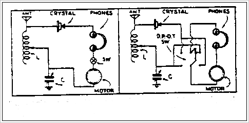
Figure 2A shows the circuit diagram using a S.P.S.T. switch for making and breaking the current. Figure 2B shows the method of connecting a D.P.D.T. switch which reverses the current at every half-revolution of the rotor and giving twice the power of the method shown in Fig. 2A. With a little ingenuity the builder can design a switch which can be thrown with a very small movement of the hand.
If a powerful station is close by, the switch may be eliminated and a commutator built on the hard-rubber rod so that a wire brush makes and breaks contact at the desired time as shown in Figs. 1A and D. The motor built by the writer has been operated on stations many miles away using the hand commutation method.
(Mr. Hall is connected with the Physics Departrnent of West Virginia University, Morgan-town, W. Va.-Editor)
