The Searl Effect Part 2 by Gunter Sandberg
The Searl Effect Part 2 by Gunter Sandberg

The Searl Effect Part 2 by Gunter Sandberg
In 1946 a basic discovery of magnetic nature was made by John R.R.Searl of Mortimer Berkshire.
He found that if a small ac component (~10^2) of radio frequency (~10^7 Hz) is superimposed on the magnetization direct current ( fig 1) during the manufacturing process of permanent ferrite magnets they acquire new unexpected properties.
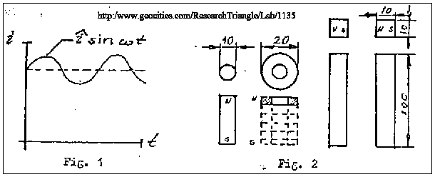
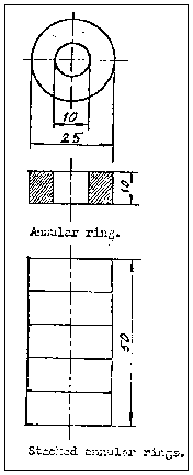
One roller was made in the shape of a cylinder 210-mm in diameter and the other consisted of a number (~ 5) of annular rings ( 20mmext. diameter )(fig 2). All the magnets had been simultaneous magnetized in the described manner.
These permanent magnets are still in existence and were demonstrated to me by Searl on August 15 1982.
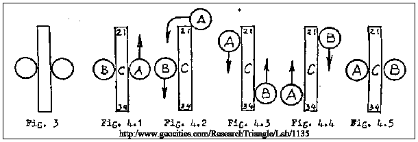
If the magnets are put together according to configuration if figure 3 they will interact with each other in the following manner. (fig 4)
If a magnet is slowly moved by an external force towards corner 1 of the magnet c (fig 4.1) and carefully pushed around the same corner (fig 4.2 ) magnet will accelerate at considerable speed, roll around corner 2 and continues its rotation and along the left hand side of magnet C figure (4.3) until it reaches a turning point ( fig 4.4)
At the same time as magnet A is pushed around corner 1 magnet B starts moving spontaneously and accelerates to a high speed rolls around corner 3 and 4 and continues it motion along the right hand side of magnet C (fig 4.3 ) until it reaches a turning point (fig 4.4) .
After magnets A and B have reached their respective turning points they will oscillate synchronously (~10ms) until they come to rest in the new position (fig 4.5) (these sentence unreadable)
The Searl Effect Generator
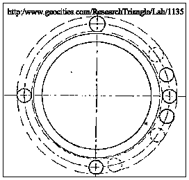
The next logical step taken by Searl was to replace the bar magnets by annular rings placing rollers around the outside (fig).
Accordingly the information given to me by Searl, the same effect is produced in the configuration as with straight bars, ie, if one of the rollers is set in motion by an external force, the other rollers start spontaneously in the same direction (fig 5)

Searl found that if the number of rollers placed around the outside of the ring reaches a certain minimum Number ( fig 6 ) the rollers are set in motion spontaneously increasing in speed until a [ [rotationally] {this word could also be meant to be [stationary] } dynamic state is reached
The maximum number depends on geometry and material parameters and I do not know it at this time of writing.
He also found that the device ,when running produced an electrostatic potential difference between ring and rollers. The stationary ring being positively charged (fig(6). Gaps created by magnetic interaction and centrifugal force ,prevented mechanical and galvanic contact between rings and rollers (fig 6)
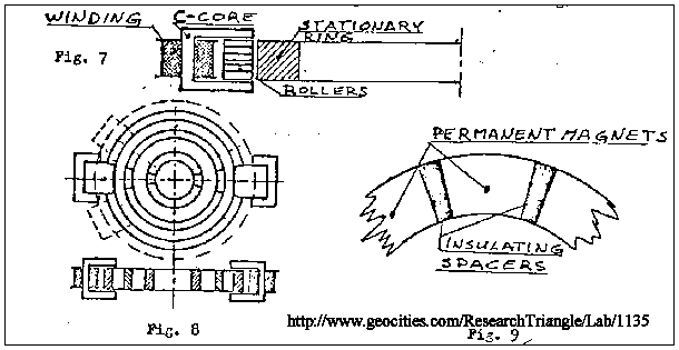
By adding stationary C~ shaped electromagnets to the Stationary ring and the moving rollers (fig 7) the device produced electric power on its own. (~10^2 watts). Several small generators of this type were manufactured and by 1952 Searl had built the first multi-ring generator.
The device was about three feet in diameter and consisted of three segmented rings in the same plane with a number of electromagnets on its outer diameter (fig 6).
Each ring consisted of a number of magnetic segments with insulating spacers between each such magnets ( fig 9 ) Due to high cost this generator did not contain enough magnets to be self starting.
This generator was tested in the open and the armature was set in motor by a small motor. The device induced an electrostatic potential in the radial direction.
At relatively low armature speeds a potential of the order of 1,000,000 volts produced as indicated by static effects on near objects.
Characteristic crackling and the smell of ozone supported the conclusion.
The unexpected the occurred .The generator lifted up while still speeding up, broke the union between itself
And the magnets and rose to an altitude of about 50 feet. Here it stayed for a while ,still speeding up and surrounding itself in a pink halo.
This indicated ionization of the air at much reduced pressure. Another interesting side effect caused local radio receivers to switch on ,of their own accord.
This could have been due to the ionizing discharges and electromagnetic induction. Finally the whole generator accelerated at a fantastic rate is believed to have gone off into space.
Since 1952 Searl and his co. workers have manufactured and tested more than ten generators. The largest constructed was 10 meter shaped craft.
Searl work has never been published in the scientific or the technical literature but many individuals and institutions know of his findings.
However a theory has been put forward by Professor S.Seike in an attempt to explain the interaction taking place in and around the generator. A patent was applied for by Searl but was later withdrawn.
Mr. Searl would like cooperation and has given out some important information. Concerning the principles of the manufacturing process of which is detailed below.
(1) During magnetization a small ac component (~10^2 MA) of radio Frequency (~10^7 Hz) and is superimposed on the magnetization direct current.
(2) At Least 180 ampere turns are needed for magnetization. (this figure may be incorrect the documents were hard to read WEB EDITOR)
(3) For normal running all magnets in the same generator must be simultaneously magnetized.
(4) The specially made magnets have a tendency of temperately changing the characteristic properties when in contact with other permanent magnets ,or magnetized with AC components of different frequencies. However after being removed from material disturbing fields the special magnets will after a few minutes ,regain their original properties. This phenomena could be used as a control mechanism
(5) Searl has pointed out that it is possible to program the behavior of the generator by magnetizing just one of the small annular rings with a different frequency. He has for instance been able to make the generator temperature dependent in such a way that it will stop running if the temperature exceeds a certain level (~50' C) a value far below the Curie point.
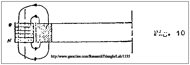
(6) Basically the internal magnetic fields is along the axis of the rollers and annulus (fig 10)
(7) Magnetic material ferrites or magnetic ceramics.
(8) Measurements made by Searl show that the power to mass ratio for the one ring generator is 180KW/ton when interacting with the gravitation pull of the earth.
Searl has proposed construction of a one-ring generator with the following dimensions.
