Telsa High Frequency Electrical Generator
In the early years when Nicola Tesla had his laboratory in New York, he made a simple vibration device powered by air. It was simple in construction and having no valves , one air inlet and only one moving part.
Although power required is hazy, it was suggested he used only 1/25 horsepower to run it.
When he had the unit connected to a metal pillar in his building and when he had it running some time, there was resonance build up enough in the surrounding buildings to cause them to shake and nearly be destroyed.
They would have happened to, if he had not stopped the unit by hitting it with a large hammer nearby to stop the resonance.
Although I have not seen the unit , I believe it could have worked in principle like the unit illustrated.
The design shown is my idea of how it could have been modified later by Telsa to generate electrical energy of high alternating frequency for transfer of electrical energy without wires.
It could be made of metal [preferably] but maybe with modern plastic fittings as well if heat build up is not a problem encountered.
The unit might have been constructed thus:
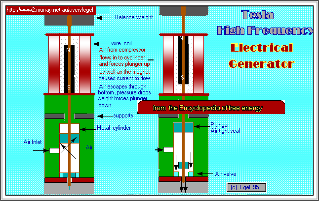
A single cylinder closed off at one end with a drill hole small enough to hold a single piston rod .
On the bottom of the shaft is a piece of plastic that seals bottom hole in position when shaft is in down position.
Next up is an air delivery position.
Further up the piston is a piece of circular metal that makes a air tight seal.
Rubber seals or oil possibly be used to ensure a complete air tight fit.
Above this is a set of magnets that move through a coil of wire.
The weight above is designed to help move the assembly down when air pressure drops.
Secure top of unit so that rod can only travel up and down without side ways movement.
A Slight Variation
The piston arrangement could be different in that no hole needs to be drilled in the bottom of cylinder.
Use a cup or tin can for outer cylinder and fed with air in from side.
Place a small cylinder inside can so that rod shaft has somewhere to rest securely and is able to move only up and down.
Make a cover that fits over top of can and is air tight when rested there when fitted to shaft. Make a inlet for the air to be side delivered into unit.
The rest of assembly is as above.
The distance the rod needs to travel need not be large as it is the higher frequencies we are interested in.
You will need to experiment with coil windings, magnetic strength and air pressure to get your desired electrical output.
Theory Of Operation
Air Pressure is delivered through side outlet
The air pressure in the cylinder builds up and lifts assembly upwards generating electricity in one direction in the coil.
When the air pressure drops due to the bottom hole in the cylinder or through the top with cup unit ,the top weight forces unit downwards and generates electricity in opposite direction.
The whole process repeats until air supply is removed. I would suggest that the Tesla unit be mounted on rubber backing to prevent vibration transfer to surrounding areas. The ideas put forward are not protected by patent as far as I know.
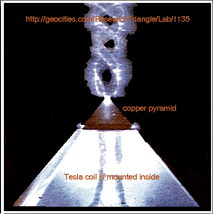
Some time ago an experimenter interested in the study of high voltage Kirlian photography produced this photograph.
A Tesla Coil is placed inside a pyramid shape as shown below in the photograph the top portion of the pryamid contain a copper shaped pryamid on top. The light display and high electrical discharge gives an interesting double spiral output don't you agree,
will place full credit name when I can get it.