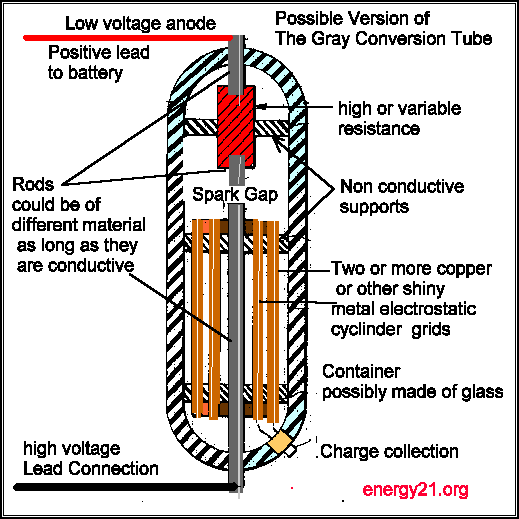


This diagram above may be the answer to free energy , that we have all be looking for and an explanation as to how the Ed Gray Device may have worked . And thanks to Peter Lindemann DSc, and his patent search into additional material of Ed Gray Patents of which it seems no one was aware until now, seems to have. uncovered something we may all now use to make some headway in our experiments towards getting free energy. This article can only be a brief outline on how it works, for a more comprehensive explanation I suggest you get the book or video entitled the Free energy secrets of cold electricity by Peter or visit the following Free-energy cc website for more information. I have also added the Gray patent from which Peter gain some insight giving as to how the Ed Gray conversion tube may have worked. This is an additional patent to the one many have seen of motor and gives some additional information on the electrical generation involved in its running . It seem now the secret to unlimited electrical energy will rest of us understanding the diagram and the information contained in Ed Gray additional patent material as presented here.. The conversion tube device is it seems powered from a high voltage DC source of several thousand volts and is fired in a pulses of extremely short duration and in a rapid succession and not allowing the power to reverse it direction of flow. The secret seems to be also in the way a high voltage discharge occurs across the spark gap causes a powerful disruption to the space and in the area occupied by the metal elements or shields. It is not known what material these metal electrostatic elements were made of or how thick they were ,but a shiny metal copper is assumed to have been used .for these electrostatic elements ,although stainless steel would probably also work as well. The metal for the spark gap rods is probably made of something common as well, and may consist only of one type of material ,but I have heard via the web that spark gaps are known to work better when they are comprised of two different metal types, for example lead and iron, this may also be case here as well The voltage must be able to travel in one direction and not be able to oscillate and find an energy balance level and cancel the effect we are looking for... If you have access to the twin books of The Nikola Tesla Patents ,Lectures and articles check out his work on his pulse experiments, I have unitil now assumed they were something to do with his high voltage high frequency experiments ,It seem that I like others have misunderstood it, and that these experiments do indeed hold the secret to free energy. Some of the results that Nikola Telsa seemed to have observed, was the formation of unusual light displays after high voltage discharges ,that it seems headed out into space. ,It is interesting to note now and just recently that natural lighting observers have just become aware of unusual light manifestation called sprites jumping into space after a powerful natural lightning discharge. The big cans of the Testatika may also be a version of this spark gap tube arrangement, the Wimshurst part of this well know machine within the free energy scene, is quite capable of generating the electrostatic charge needed and could also be the secret that up to know has been kept hidden from the rest of us,. Could it be really as simple as the diagram above.. It is common knowledge that when a terminal is closed on high voltage dc power circuit there is enough energy released at time of circuit closure to kill the person throwing the switch unless special precautions have been taken (where did this excess energy come from ) after the contact switch has been successfully thrown the danger is no longer there , the system now acts as it was safely designed too.
Published by
1. The Electro-Radiant Event is produced when a high-voltage, direct current is discharged across a spark-gap and interrupted abruptly before any reversals of current can occur.
2. This effect is gready increased when the source of direct current is a charged capacitor.
3. The Electro- Radiant Event leaves wires and other circuit components perpendicular to the flow of current.
4. The Electro-Radiant Event produces a spatially distributed voltage that can be thousands of times higher than the initial spark discharge voltage.
5. It propagates instantaneously as a longitudinal, electrostatic "light-like my" that behaves similarly to an incompressible gas under pressure.
6. Electro-Radiant effects are solely characterized by impulse duration and voltage drop in the spark-gap.
7. Electro-Radiant effects penetrate all materials and create "electronic responses" in metals like copper and silver. In this case, "electronic responses" means that an electrical charge will build up on copper surfaces exposed to Electro-Radiant emissions
8. Electro-Radiant impulses shorter than 100 microseconds are completely safe to handle and will not cause shock or harm.
9. Electro-Radiant impulses shorter than 100 nanoseconds are cold and easily cause lighting effects in vacuum globes.
Thanks for linking to my site. I really appreciate the support. Just a
note to clarify your excellent diagram. The top electrode in the tube
actually is connected to the positive of the battery, not back to the
"high voltage source" as you indicate. Gray called this his "low
voltage anode."
Also, from the photographs we have, it looks like Gray had at least 4
grids in his tube. We're making a lot of progress. One friend of mine
fried a 1000 amp meter with an impulse from a system whose input was
less than 12 watts. Another person reported to me that he had so much
electro-radiant event backing up in his primary, it kept his capacitor
charged, and the system kept running even after he shut off the supply.
We are definitely getting close.
I'll keep you posted. Thanks again for the support!
Sincerely,
The following information has been taken from the Book The Free Energy Secrets of Cold electricity by Peter A.Lindemann, D.Sc
Clear Tech inc
P.O.Box 37
Metline Falls WA 99153
Summary of The Electro-Radiant Event
A email message from peter
Peter Lindemann, DSc

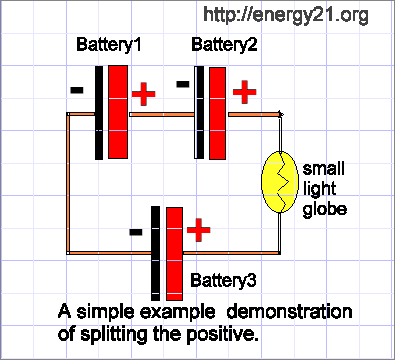
It has come to my attention that Edwin Gray when describing the workings of his device used a term called SPLITTING THE POSITVE to explain how his device worked.
I have been drawn to the attention of a simple circuit as above that apparently Jerry Decker has at his website for some time that may explain the resulting action . keelynet.com
I have tried this experiment myself as per link below.
I would suspect the battery sizes are not critcal but personally I am going to use three six volts batteries as they seem to be the easier to connect as above.
Two Batteries are connected in series that positive lead is connected to negative lead and so on. The third battery connection negative to negative.
So now that you have two leads free that come from the positive side of the third battery and a postive lead from the other two batteries as per circuit diagram.
These two leads are then connected to a small lamp as shown in circuit diagram.
I am going use a lamp globe rated at 6 volt's
The circuit is simple enough so other's reading this may like to try this for themselves and then let me know how you get on.
My experiments using the above circuit
If you try some of the experiments related as above please let me know how you get on.
