
This invention was presented to an audience at the inventors weekend 2001 at La Quinta Inn, as run by Bruce Perreault of Nuenergy
My understanding of the device has been obtained from watching a video of the demonstration and lecture by inventor ,if you are interested you can obtain a video from Bruce at the above web site link.
This is my understanding of the device although I may have missed something along the way .
Warning
Playing around with charged capacitors is extremely dangerous and may result in loss of your life if handled incorrectly.
This material is displayed for educational value and no claims are made for its accuracy so please carefull..
One tip when using high voltage is to use rubber gloves and keep one hand in your pocket at all times to stop a high charge going through your heart.
At the conference there were no claims made that this was a free energy machine although some details obtained may indicate otherwise.
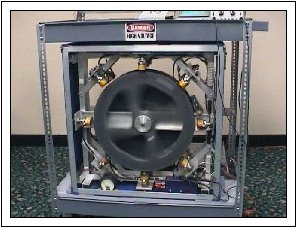
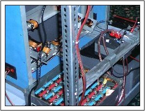
The Device appears to be twin connected rotating disks with 32 Neo Iron Boron magnets grade 30 of approximately 11,000 gauss each. and attached to rim of each wheel. and placed on a frame assembly.
There are 32 magnets to each disk mounted at 11.25 degrees separation from each other as indicated in the drawing making 64 magnets in total .
All magnet face outwards in a (N) north pole direction.
Positions in degrees are as follows
0,11.25,22.5,33.75,45,56.25,67.5,78.75,90,101.25,112.5,123.75,135,146.25,157.5,168.75,180,191.25,202.5,213.75,225,236.25,247.5,256.75,270,281.25,292.5,303.75,315,326.25,337.5,348.75
I not sure of the size of magnets but apparently in 2001 they were costing about $5.00 each.
DRIVE COILS
There are four drive coils positioned 12 ,3,6,9 o’clock positions these are connected in parallel and pulsed fired together to drive the wheel.
The coils in this unit are mounted 3/8 inch from the magnets on the drive wheel but they may also be needed to be adjusted to allow for the magnetic speed drag reduction between the magnet and the coil.
Although not specifically mentioned I think there would need to be some sort of trigger to fire the driving coils whether be a magnetic pickup coil, or optical trigger or even a simple switch.
This unit run in an attraction mode but apparently a repulsion mode is feasible as well I also think the coils would need to fired before being directly opposite each other.
There are an additional four drive coils mounted at the same position for the second wheel of the device as well, one would assume these too are connected in parallel with the other drive coils on the front wheel although not specifically mentioned as such..
This makes 8 drive coils in total.
Output Pick Up Coils
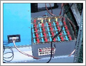
There are four on each drive wheel mounted in a position between the drive coils as per diagram making eight in total and connected in series to give an output of approx 100 volts this is the rectified to give a pulsing dc output that then charges a 1/8 farad capacitor bank consisting of 50 2400 micro fard capacitors of 450 working voltage.
Core material
Calvin mentioned using core material for the coils but did not say what he was using but I myself will be trying some ferrite rods myself.
If the combined output of the eight pick up coils is 100 volts then this means each coil needs to be an output 12.5 volts each , I not sure at what current level but doubt it very high ,may be in the milli amps range.
I believe the entire resistance value of entire output section is 1480 ohms making each coil in series of 185 ohms each.
I believe the inventor acquired these as disposal solenoid coils
The speed of the twin disks spins at speeds varying between 350- 400 rev per minute.
The voltage input to the device varies from 12 to 48 volts but would ideally runs at 24 volts suiting alternative energy systems.
The current produced is apparently 115 milli amps but has been running slower at 3 milli amps according to inventor.
Calvin also demonstrated the wheel using a small 9 volt battery although I think wheel speed did slow down but continued to run.
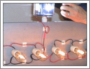
Calvin was also shown discharging the capacitor bank and producing ark lighting as well as powering a bank of lights.
SOME DETAILS IN BRIEF
TWIN PLASTIC WHEEL of unknown size
64 Neo Iron Boron magnets grade 30
8 drive coils
8 power pick up coils
speed 350-400 rpm
Input power 12-48 volts
Output power 100 volts DC rectified and used to charge capacitor bank
115 milli amps.
I think the intention is then to drop this voltage and charge the battery bank.(this was not made to clear in the video)
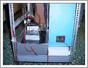
Capacitor Bank consists of 50 2400uf 450 working voltage capacitors.
Weight of machine 181 pounds. Not sure if this refers to disc section or entire device.
The device also has a 35 amp 100 volt diode protection on capacitor bank.
The device is not a self starter.
The photos on this page have come originally from Bruce Perreault website and I did the diagram based on my understanding of what was conveyed from the video as purchased from Bruce.
Tips for others:
You may not be able to get a plastic wheel but the following may be of some help.
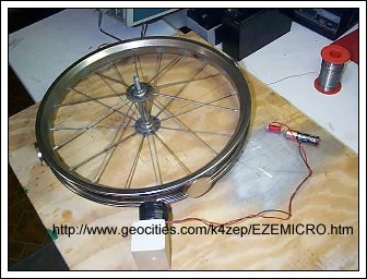
another experimenters and his eze mirco drive wheel eze mirco drive wheel
He has been using a bike rim to make something akin to the power wheel but aiming to make a drive wheel for testakica type machine.
I myself am trying to make a power wheel myself using 36 ceramic ferrite magnets and 4 ferrite pickup and 4 output coils and some large store bought capacitors. and a bike rim in a manner indicated in the last photo.
Please note even charging a 8000uf capacitor with 6 volts for brief period of time is enough to make it spark when leads are. crossed.
I am hoping with a bank of these when connected and fully charged in parallel with give me enough power. to pulse power the drive coils with pulse.
Anyone out there who can help me with coil design please let me know.
Especially a design to use a pickup coil to pulse my coil drives
Anyone out there with some large value working capacitors and does not want them anymore , I would be happy to have them, I afraid I not I a position to pay for them.
Geoff Egel
18 Sturt Street
Loxton 5333
South Australia
Australia
