The
The
By Jean-Louis Naudin
created on September 20th, 1999 - JLNLabs - Last update September 20th, 1999
Variations on the PFT Motors ofJean-Louis Naudin by
It has become clear from Jean-LouisNaudin's research on asymmetrical electric fields and theBiefield-Brown effect that the primary driver is the Poyntingvector. At least this is the way it appears from the models hehas built to test the effects. So the breakthrough we have allbeen waiting for is the evidence in JL Naudin's tests that showsus how to use the Poynting vector from the vector relationship ExBxS.
For those not up on electromagnetics vector language you say this E-cross-B-cross-S.This means that all these vectors have directions orthogonal or90 degrees from each other. You can see this from Jean-Louis'diagram.
It is simply a matter of setting upan electric field (E) and a magnetic field (B), allowing thePoynting vector (S) to be in the right direction and thenstimulating or creating an asymmetry. Once you have an asymmetryderived either from the shape of the object (ARDA project) orfrom motion (PFT MK1, MK2 motors) you can then extract energyfrom the Poynting vector (S). To my knowledge his has never beendone before in quite this way. The S-vector has been ignored allthese years with the focus on magnetic (B) and electric field (E)vectors.
Therefore, I think that those of us that are able should initiate some independent tests ofvariations of these structures. Perhaps we can find the optimum structure quickly this way. I am making some suggestions based onthe ExBxS vector relationship for rotating systems with theintent to find an overunity power generation system.
There are several things to betested. I will itemize some here. If you have more ideas feelfree to put them forward.
1.
Purpose: To find efficient ways to maximize the use of the S-vector
2.
Purpose: Check to see if torque is increased due to two E field vectors at double the original setup.
The S-vector would be in the direction of rotation currently seen for both sides and should be twice as much giving a 4x increase in speed and torque. If it turns out to be only double the torque then it means that the S-vector flows in or out from both sides of the ExB intersection and the motion sets up the asymmetry in the required directions.
3.
Purpose: To see if enhancing the B-field enhances the PFT MK2 motor power output.
The B-field is weak with only 99ua in the present PFT MK2.
4.
Purpose: To check for Newtonian reaction forces related to the S-vector flow. If so then it is all relative motion and many variations are possible.
5.
Purpose: See if multiple electrodes increases power output and how much current is used.
Also, checks the Newtonian reaction forces if all cylinders are allowed to rotate.
6.
Purpose: Check for relative motion, Newtonian reaction forces, current drain on power supply, and possible application to Searl SEG type device.
7.
Purpose: Determine the mathematical relationship of speed, power, and voltage.
8.
Purpose: Test the theory that the SEG prime mover is really the S-vector and not modulated magnetic fields and that constuction can be simplified and operation controlled by E-field reduction or reversal.
The principle of ExBxS appears tobe identical for the ARDA project, the PFT motors, and the SearlSEG. The vector relationships are the same for all. As a resultit seems prudent to have many independent tests being done aroundthe world. Construction is simple and testing easy. Associatedcosts for materials should also be low. Let's do it friends andget the world off of burning up fossil fuels. There are muchbetter uses for oil than creating CO2, NO2, Ozone, and smog.
The PFT Motor mk1, the basic design.
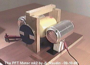
The PFT Motor mk2, an enhanced high speed version...