
A word of warning
If you fill a closed container with an explosive gas mixture, as an example one (1) part oxygen and two (2) parts hydrogen you will have set the stage for accidental explosion.
Hydrogen and oxygen can and will explode with violent effect.
To know of this, and to teach this, and not carefully warn all parties is to ignore your place as scientific ethical investigator.
My Experiments with hydrogen/oxygen gas.
I have been experimenting with this setup as described below.
Whilst the gas output volume of this unit is not great due to the low powered solar cell, I am using to power the electrolysis part of the unit <2> it does seem to work.
I would have preferred to have used stainless steel fitting in place of the brass one as I feel over time they may corrode with the contact with the caustic soda and water.
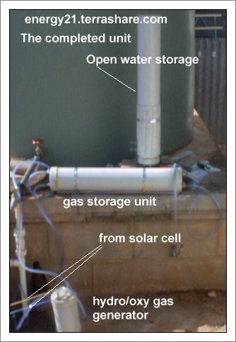
The Unit consist of four parts<please refer to diagrams and photographs>
You should be able to get everything you need to make this unit from a plumber or hardware store apart from the stainless steel mesh and the solar cell.
Make sure end caps are glued securely as water may not leak from end caps when press fitted together,but if there is any small open gaps on the end caps the gas will then force the water out,and the unit will not function correctly.
The Solar cell is rated at 36 watts 12-17 volts at 3 amps
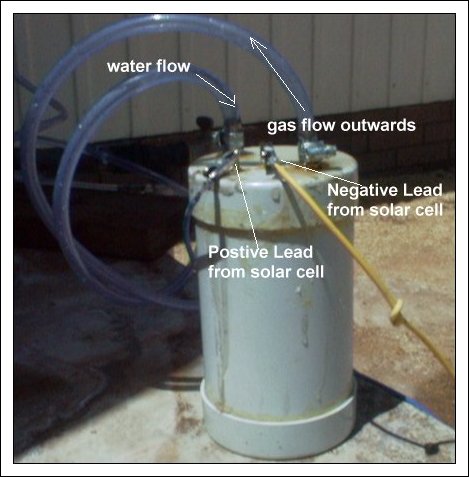
GAS GENERATOR UNIT
The gas generator is a piece of 7" by 4" inch diameter plastic storm water pipe with end caps
The electrodes are made of stainless steel punched out fine mesh there are 4 pieces rolled into cylinders of 1" diameter 2"diameter 3" diameter and 4" diameter and each piece is five inches high.
If you wish to experiment I don't believe the height is critical but the spacing could be ,I guess a little more experimenting is called for.
I would have preferred to have had them welded closed but unable to find anyone that could do it for me. ,so I used some stainless steel wire to hold them closed.
The diameter are held apart with some plastic tubing jammed in.
All flexible clear plastic tubing used is �" approx.
The inner 1" inch stainless steel cylinder has a negative terminal from the solar cell connected to it
The outer 4" inch stainless steel cylinder has a positive terminal from the solar cell connected to it as well.
On top end cap the power leads from the solar cell are terminated by means of brass screws tightly fitted into the plastic cap and screwed through and joined with stainless steel leads to the internal stainless cell cylinders inside the storm water pipe.
The tap end cap has also two brass fittings
The brass connections come with a screw thread on one side and the other side allows a plastic hose to be connected to it and secured with a hose clamp.
To Put these in the plastic end caps ,drill a hole in the plastic end caps slightly smaller the than the outer diameter of the brass fitting
Then use the brass fitting thread end to tap the previously drilled hole and then screw it up tightly so that it is air tight when plastic hoses are connected to it later.
It may be advisable to position an extra internal connection on the water return inlet to allow the water level to be lower than the gas outlet fitting.
A perhaps better way of producing gas by means of electrolysis described at bottom of this page. But I have not tried it yet.
The idea of this construction comes from the lessons learnt from the Joe Cell although this one will function as such.Please before sealing unit add some caustic soda (lyre> or baking soda to help with conductivity of the water when introduced to the unit at start up phase later on. .
Hydrogen Gas can also be produce by dissolving aluminum in caustic soda and water.(not applicable to this set up) but this design could be modified to this however.
WHEN USING CAUSTIC SODA PLEASE BE CAREFUL AS THIS WILL CAUSE NASTY BURNS IF EXPOSED TO YOUR SKIN.
GAS STORAGE VESSEL
This a length of plastic storm water pipe with two end caps secured in placed to enable it to be
airtight .
On each end of the 4" storm water end caps are placed with two brass pipe fittings placed on the top and bottom of each end cap as per photo below.
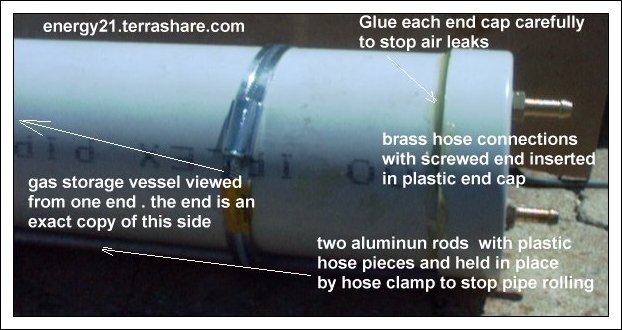
There are two fitting on each end cap. (top and bottom)
On end One.
One plastic tube from the gas generator (gas outlet) is connected to top most position of the gas storage vessel
The Lower position is connected to water return pipe to the gas producer.
One end two
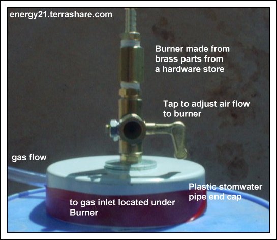
The top most fitting is connected to a gas outlet fitted with a tap.
The lower fitting is connected to an open water holding tank.
PRESSURE BALANCE AND RESERVE WATER SUPPLY.
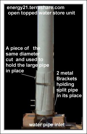
This can too be made from a storm water pipe fitted with one end cap and one brass fitting and plastic return tubing..
The height of this storm water pipe and water within with determine the gas pressure.
The higher water the greater the gas storage pressure in the gas collection vessel assuming the gas producer is able to produce gas under this pressure.
But in any case there should be enough water at start up, in this container to fill entirely the gas collection vessel.
Startup .
Make sure all plastic �" pipes are connected correctly as per diagram and that there is some caustic soda in the gas generator vessel.(no water as yet.
Make sure gas supply tap is completely closed.
Fill water reservoir completely to the top.
Turn on gas supply tap and you should hear air rushing out as water supply is filling up the gas collection vessel.
When you see water coming out of your tap
Then turn this tap to off off.
Connect the solar panel or power supply electrodes to to gas producing unit.
Now as gas is produced it will flow to the gas collection vessel , and the displaced water in the gas collector will be returned to water reservoir.
This is also a safety method as if you produce excess gas it will also be released safely through this feature.
If you don't overfill the water storage vessel you should be able to gauge how much gas you have by how much water is returned to the water storage area.
The water here will also be use to push your hydro/oxy gas out of you gas collection vessel when gas supply tap is turn on.
At first when you now open you your gas tap you will get a mixture of air and gas , and you may need to waste all of this until all the air is displaced until you get your hydrogen oxygen mixture.
Please be warned this Gas of this type can be extremely dangerous
A possible better Gas Generator
You take two pieces 200mm x 900mm and weld a connection to the end of each one. Then take a piece of flexible plastic (Similar to that from a milk carton) and punch holes in it similar to meat safe material...The plastic should be 250mm x 1Mtr. Using the roll of plastic as an interleave with equal overhang on top and sides.
Roll the whole thing up as tightly as you can. -------------------------------------------------- webmaster's note I tried using this idea using a single layer of plastic shade clothe and wound the clothe layers and electrode cyclinders together but was unable to get any gas out of it. I suspect the single layer plastic shade mesh trapped the gas bubbles and would not let them escape,using two or more layers of plastic mesh between the electrode and criss crossing the plastic mesh may be a better idea. Geoff ---------------------------------------------------------------- The roll can then be secured using plastic tie's.......The size of the roll then dictates the size of the chamber that it fits in to.(Not the other way round).The top and bottom caps can be fitted in the normal way. He suggests that this method using the fine stainless steel mesh, will give you a 32 x increase in hydrogen output over flat plates for the same electrode area..However because of the increase in hydrogen output you then need to fit a separate trickle tank of water and a float valve to ensure that the water level in the electrolyser stays above the electrodes......
He seems to think that the hydrogen pressure will not go above 14psi and so will not be a problem when the engine demand is low.(Way below the level needed to blow the electrolyser apart)...However I must admit to favouring the addition of an acetylene type flash back arrester on the hydrogen line just prior to the carb to be on the safe side.
My mate didn't think it needed it , but better safe than sorry.
Somebody on the web page said he was hearing a hissing noise from the anode and cathode when he used mesh . This would be normal excitation of the weave of the mesh as the hydrogen bubbles formed on the knuckles of the weave causing the mesh to vibrate.......If you take a piece of mesh and wiggle it like a wobbly board you will hear the same noise.....
Nothing to get up tight about, just a sign that you've increased you hydrogen output .....Hope this helps in some way..........
Best of luck with your project, hope to start on mine shortly as I get more information from Graham Snook.........
Ed Hurley. I tried using this idea using a single layer of plastic shade clothe and wound the clothe layers and electrode cyclinders together but was unable to get any gas out of it. I suspect the single layer plastic shade mesh trapped the gas bubbles and would not let them escape,using two layers of plastic mesh between the electrode and criss crossing the mesh may be a better idea. Geoff
part six of this article warning please read first
THIS INFORMATION IS SUPPLIED FOR EDUCATION PURPOSES ONLY AND NO RESPONSIBLY WILL ACCEPTED BY THIS AUTHOR FOR ITS MISUSE.
Have Fun and be care full
Copyright Geoff Egel 2000
Webmaster comment:
I am now tending to think to high voltage uni direction pulse is the way to go as per Stanley Meyers,tend to to think that the Edwin gray pulse generator that he used in his motor generator may be the device to accomplish the desired high voltage low current pulse.
You are right about the pulsed high voltage. But not for the right reasons. High voltage, low current
is not the answer since the gas production is current related.
However, if you fire a high voltage across the electrodes using tap water or better, distilled water, and also have a low voltage, high current source impressed on the electrodes, the high voltage will create a path for the low voltage/high current to follow,thus liberating more gas with each pulse.
The pulse rate with determine the intake manifold pressure, which in turn will give varying rpm. Higher manifold pressure=higher rpm's.
The system should be closed loop, with no outside air used in the combustion process. This eliminates nitrous oxides from exhausting the engine, actually you will have no exhaust, but will condense the water vapor formed from combustion and return the resulting water to the fuel tank, giving a very high fuel mileage on a tank of water.
The only limiting factor here is the battery power and what methods you use to resupply it.
The obvious electric supply would be an alternator, solar cells and recovering exhaust heat in an electrical form.
The latter is what we are hard at work on and the one area I must remain close-lip about. Good luck----JOHN
The correspondance that you posted touched on a good point, but didn't follow it far enough.
The separation of gasses is key to your safety in this experiment.
An explosion is caused by the rapid oxidation of the hydrogen (burning).
If you were to collect the oxygen and hydrogen separately, or just vent the oxygen, you would have pure hydrogen, which, in the absence of oxygen, can't really do all that much. ,
Of course, leaks in the system can re-introduce the oxygen to the mix and make for a nice bang... or not so nice bang.
It has been a number of years since I took Chemistry and Physics, however, I do remember that oxygen will be released from the water during electrolysis at one of the electrodes, and hydrogen at the other.
It should be simple enough to look it up on the web or in a chemistry or physics text. One thing to consider is that oxygen has roughly 16x the atomic mass of hydrogen, thus taking up considerably more space.
It would be fairly easy to tell which is which through experimentation, though it
would be much safer to do your "homework" ahead of time.
Check out web elements.com as a starting point. As with your combined gas generator, you will have to keep this fairly well sealed, and if you intend to keep both the H2 and the O2, you'll need to construct separate storage tanks.
The models you have on your page look like they would work nicely for this. Cheers, -Eric. :)
P.S. BE CAREFUL. Say it, think it, act it,mean it, live it.
