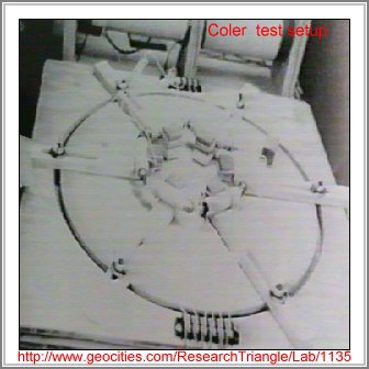
This device called the magnetromapparata was invented in 1933. It needed no outside power sources to function. Since an official interest was noted from the heads of the German navy at the time who felt an investigation was necessary and an official report was produced. Experts examined the device and could find no fraud. It was judged Coler was an honest experimenter but no expert opinion was forth coming to how the unit operated.
The device consisted of permanent magnets of steel ,copper coils and capacitors in a special holding arrangement. The device incorporated six steel magnets in a six sided arrangement where the magnets were connected in series with the coils of about .33 ohm resistance to form part of the circuit. That is a conducting path was made through the magnet core. The design also incorporated two small capacitors, a switch and a pair of sliding solenoid coils , one fitting inside the other. as shown in illustration. To allow the device to power up the following was done. The switch was left open. The magnet and coil combination were moved slightly apart using a mechanical arrangement of cranks and sliders that allowed each magno coil combination to be altered equally, There was a wait of several minutes between changes. The sliding coils were also set to different positions relative to one another. These changes were made often until a precise point was reach as indicated on the voltmeter. The switch was then closed. There were still more changes more slowly this time until the best result was achieved. Several tests gave the 450 millivolt for period of some hours other times 60 millivolts was all they could get. The best voltage obtained was about 12 volts and remained there indefinitely until the unit was shut down. I believe that this device has some similarities to the Hendershot design. Coler was also said to have created a device called the stromerzeuger. This consisted of a arrangement of steel magnets, flat coils and copper plates on open arms mounted in a parallel combination with one another and fed power from a tranformer from the centre.. The output is said to have lit a blank of lights of which the output exceeded the input power level. He was said to have built a 10 watt unit in 1925 and a 70 watt unit in 1933. Other units followed until the end of the war where work seems to have come to halt.
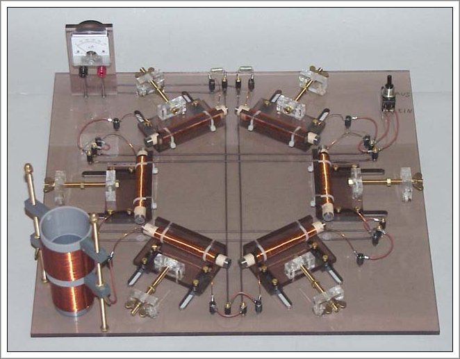
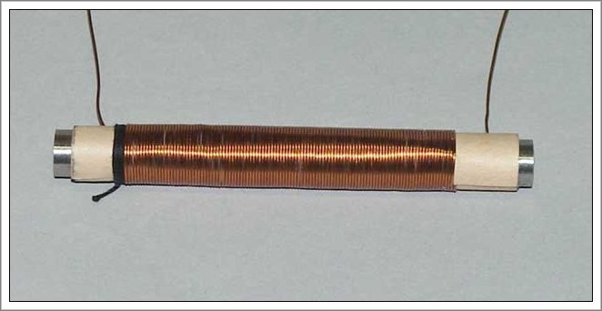
An experimenters attempt at reproducing the device as described above.
Their results are unknown at the moment
One interesting note has come to hand from a correspondent named
"Steve who has informed me that
" The device had a radio active coating this information may have been left out of the British Intelligence Report where my information came from. It seems that other free energy devices from that time Hubbard and Hendershot among them may have had radium included in those devices according to some. Usually the wiring is coated with a radium chloride or the likes to reduce resistance to practically zero. Also, if it is used in a capacitor, it then acts more like a semiconductor. Using it in the core's of transformers does the same as the wiring trick plus a little more. As far as an antenna type of scenario, the wire now ionizes the surrounding air around the antenna wire like a bubble that is saturated to the max, thus any input from the atmosphere or anything, adds its energy to it. Steve claims that he has done it and it works! As far as experiments go. He did simple things like measure the resistance of a piece of wire and then did it again with the radium chloride. More times than not, the resistance was zero or a negative deflection. OH, BY THE WAY, STEVE SAYS DO NOT USE DIGITAL METERS, the capacitors act like semiconductors as stated earlier and the meter will go on the fritz for a few days before returning to normal. I promise! I set up another experiment where it was a complete circuit and then made a one inch gap and placed a vial of radium chloride about another inch away from the gap and the circuit continued to function! Anyone can do this and will get the same results."
Thanks for information STEVE
from ASW
I have built the thing,but need to invest in a digital CRO to tune it ($1000+).My net acess is very restricted (but will keep in touch) There is a lot of fake info floating about. I sent for documents,which are copies of the original in the imperial war museum in the UK.
The informatioin in the free energy encyclopedia is incomplete ,you need more info.
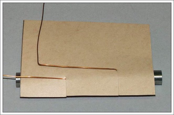
The diagram of the coil winding should not be dimensional and is nowhere near scale.
There is a lot of talk about coating on the wire but it is misinformation.
The device should work as described but it must be made as a resonant circuit,which is tricky but because it works best at certain frequencys, also the electrical wavelength of the circuit of the circuit helps efficiency also.
Some of the best people to talk to are Harold Aspden in the UK and some of the US keelynet people. I am keeping an eye on material by Tom Bearden as he covers the theory side rather well I am looking at some stuff now which is related to coil winding ,mirror image and in parralell ,looks promising. (on The I.N.E sits
Regards ASW
An experimenters attempt to reproduce the coler device