
AN UPDATE ON THE CONTINUING RESEARCH INTO T. H. MORAY AND
OTHER FREE ENERGY DEVICES WITH CONCLUSIONS
Placed on this web site with permission of author.
ABSTRACT
At the Tesla Symposium last year I gave a report on my research into the T. H. Moray Radiant Energy Receiver . Over the past year and I have continued my research into T. H. Moray but have also branched out to other free energy devices because of the facts I have uncovered in my various researches.
I have researched all of the relevant books, periodicals and other references that I could find from 1880 to the present. Some of the books that I have found to be of the greatest help were the books by Gustave LeBon, Rutherford, Curie and of course T. H. Moray. There are many other books I also found valuable but the list is to great to go into here. You can check my web site for more information on these books. Most of these books were so hard to find that I decided to start a publishing company to reproduce these books and many more including new books by Dr. Paul Brown, Rodney Sego and several others currently researching free energy. Both Dr. Paul Brown and Rodney Sego have just written new books on their researches into T. H. Moray and both of these books just became available as of May 15,1997.
One of the things I have found that seems to be constant with all of the free energy devices that I have researched is radioactive materials. These devices include not only the devices of T. H. Moray but also those of Hubbard, Hendershot and Testitaka. Even the increased power of the new neodymium and samarium/cobalt magnets can be traced to radioactive materials. Radioactive materials appears to be one of the keys to free energy.
I will attempt to cover all of these devices in a logical manner. Because of the time allocation here today I will have to cover some of the items rather quickly. I will be giving a more thorough coverage of each of todays items and a lot more subjects in the book I am presently finishing. I hope to have this book completed later this year. Also I will have copies of this speech complete with all of the overheads available at my booth for anyone who wants them. My booth is in the main exhibit area and all profits from the sale of books I offer will be used to further my research.
Before getting into each individual device I would like to pass on a few general observations and conclusions that I have reached as a result of my years of research into the alternate energy and free energy fields. It would appear that the time span between 1900 and the 1ate1930’s was a very prolific period with a lot of people trying to develop power sources using the newly found radioactive materials such as Uranium, Thorium and Radium.
These include Perrigo who invented his first unit 1915 and who by 1922 had demonstrated a unit which produced 4500 watts. He died shortly thereafter taking the secret to the grave with him. Another is T. H. Moray who produced his first unit in l9l0 producing 8 watts and by 1925 had a unit producing 650 watts. Moray went on to produce a unit in the late 1940’s that produced 3000 watts. Next was Alfred Hubbard who built his first unit in 1919 producing less than 100 watts and by 1926 had demonstrated a unit producing 26,000 watts. He sold all rights shortly after that and disappeared, again the technology was not developed. Last was Lester J. Hendershot who invented his first unit in 1928 producing less than 100 watts and had a unit producing 300 to 500 watts in the late 1930’s and a final unit producing about 1000 watts around 1950. Hendershot’s son Mark is presently working to reproduce the device.
Had I have relied on modern text books a lot of the data presented here today would not have been possible. It was only after studying the works of the great researchers of that era like Rutherford, Chadwick, Lind, Geiger, Crowther and especially Le Bonn’s books that I had a good insight into the awesome amount of knowledge that was discovered during that period in history. After searching out these books, some of which were almost impossible to find, I can clearly see why so much research on free energy was done during the time from 1900 to 1940.
Also during that period radioactive materials were easy to get because the government did not have the strict regulations they have today. At that time anyone could go to the hardware store and buy Radium paint to make their light switches, and any thing else, glow in the dark so they could find them easily in the dark. With all of this information and the materials needed so readily available there were a lot of people conducting research. I urge every serious free energy researcher here to thoroughly study the books of this era. The amount of information in them is truly awesome. If anyone wants a list of these books please come by my booth and I will give you a copy of the list.
I would like to start with the T. H. Moray device. This is the device I call the Holy Grail of free energy research and is the device that I have devoted more research time to
this than any other device. It is the device which has gotten more coverage than all of the other devices combined even though there were other devices more powerful and were invented ahead of him. I will not be giving a boring history lesson on the already known facts of this device that have been beaten to death over and over in many books and by many speakers over the years. I will attempt to give only new information, some of which has never been divulged in public before today. I will attempt to cover as little of the well known history as possible, using only those items that are necessary for a more complete understanding of the new information I am going to provide.
Before I get too involved in the construction details of the Moray devices I feel that there needs to be some clarification on the various publications put out over the years by the Moray family. I will take these in reverse order, the reason for which will become apparent shortly.

The most recent publication was "The Sea of Energy in Which the Earth Floats" fifth edition. This was published in 1978 by John Moray, T. H. Moray’s son.
This was the fourth edition of "The Sea of Energy in Which the Earth Floats". This was published in 1960.
A book called "Radiant Energy " For beyond the Light Rays Lie the Secrets of the Universe" was published in 1945 and 1956.
Before 1945 Moray published several printings of a small pamphlet called "Beyond the Light Rays" which was first published in 1931.
The 1931 publication was the first edition and the 1945 and 1956 books were the second and third editions respectfully and the fourth and fifth editions were as labelled. This is confusing because one does not normally change the title of the book from one edition to the next. But then anyone who has known either the father or the son will tell you that strange is only the beginning. All of these editions are good reading. However most experts in the field agree that the fourth edition is the best. The fourth edition was the last one to be written by T. H. Moray himself The fifth edition is an edited version of the fourth edition with some things not the same as in the fourth edition. The only new information that I have been able to find in the fifth edition is page after page of testimonials and hype on how the Morays need financial help to finish T. H. Moray’s work. I did find a couple of things useful in the fifth edition, however I will get into these later.
In my research I found Moray only built a total of four devices. The first device appears to have been built around 1910. This unit produced about 8 watts. Of course you must remember in those days the FCC did not exist and radio stations were few and far between. These stations could pump out as much wattage as they wanted to. Many stations put out so much wattage that it was dangerous to be too close physically to the transmitting tower.
With this in mind it is not hard to see how he could get 8 watts out of an antenna that was 70 feet high and over 100 feet long receiving a signal from a powerful radio station only a few miles away. In 1912 he went to Sweden and returned in 1913. While in Sweden he supposedly found his "Swedish stone" that allowed him to draw more power than before.
Later in this talk I will give you my thoughts on exactly what I think the stone was and where I think it came from. Using this stone in the early 1920’s he built the first generation unit which produced about 25 watts using a modified crystal radio with the output going to a light bulb instead of a speaker.
He kept on refining this unit until he could produce 100 watts by 1925 This was the second generation unit.
This is the third generation unit which is again nothing more than a modified crystal radio which is now hidden inside a wooden box. He kept improving this same unit until it could produce around 650 watts for short periods of time. This 650 watt unit is the unit that all of the testing by Harvey Fletcher and many others was done on. This is the only unit that was ever tested for long periods of time. This unit and the fourth unit were only ran for short periods of time, usually only a few minutes and never for over one hour at a time with more than about a 200 watt load.
The fourth unit could produce a lot more power but it had the same limitation of overheating on long runs at full power output. Again this unit could be ran for long periods of time but only with reduced loads of less than 200 watts to keep the unit from overheating and burning up the "Swedish Stone".
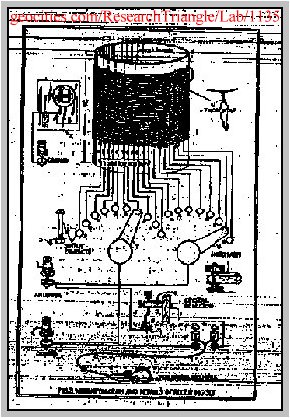
Let us now take a closer look at this second generation unit and see how it was constructed.
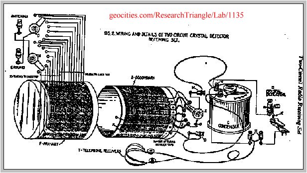
This is a picture of this unit. As you can see its construction was typical of crystal radio receiving units of that period of history. In order to understand how it was constructed I went back to the crystal radio construction books of that period. The best information I found were these 3 publications from the Bureau of Standards.
The first is a book called " The Principles Underlying Radio Communications". Although it is called pamphlet #40 is over 600 pages of some of the finest radio principles and radio set constructions plans of that era. It was first published in 1918 and this second edition in1922. This was the bible of radio construction of that era and would definitely have been used by Moray in the construction of all 4 of his devices.
These two circulars also from the Bureau of Standards numbers 120 and 121 which show the detailed step by step construction and operation of a radio receiver of that era.

The patent application date July 13, 1931 as shown on pages 129 through 133 of the fourth edition. I have searched the patent records as well as I could but I can not find a record of Moray’s application. There probably was a patent application in 1931, however it is my opinion that it was for his earlier unit which used the Pickard type of detector and was denied because of Pickard’s patents. It is sad that we may never know the real story and exact time line here because of John Moray’s obstinance in releasing any information on his fathers work. With as many people researching his fathers work as there are today the story will eventually be pieced together. The sad part is that there is a good chance that a second Moray will take the complete story to their grave with them. It is my hope that John Moray will see the light and release all of his fathers work before he dies, however having talked with him and met with him on several occasions over the past few years I will have to say that this idea has about as much chance as a snowball in Hades. Perhaps if enough people contacted him we could change his mind.
One of the few things I found of value in the fifth edition was a passage that leads us to the next stage of the development of the Moray devices. I quote from page 186 of the fifth edition, "In 1942, shortly after World War II began for the United States, Henry Moray attempted to rebuild a Radiant Energy Device using the remaining bit of what was known as the "Swedish Stone". This material, which was the heart of his original RE detector, he had never been able to duplicate, and the shortage of this material limited the amount of power he could draw. Consequently, in the larger unit, he developed a second detector that forced him into extensive research involving nuclear materials and radioactive reactions .
From this we see that Moray had used up most of the "Swedish Stone" he had brought back from Sweden. Actually he did not use it up, he burned it up. Every time he tried to
draw large amounts of power for sustained periods of time he would burn up the piece of "Swedish Stone" he had in the unit at the time. By large amounts of power I mean anything over 200 watts for more than an hour of continuous running. He could draw larger amounts of power, around 700 watts, for short runs of only a few minutes without burning up the "Swedish Stone". There are several accounts in the Fletcher files of him burning up the "Swedish Stone". At least one by Moray himself From page 188 of the fifth edition I Quote " Meanwhile the RE device had burned out during a test in Salt Lake City because of an overload in the circuit. The so called detector was no longer operative" End of Quote.
From all of this we see that before the end of the year 1942 Moray had destroyed the last remaining bit of the "Swedish Stone" and was forced into research. This means in the 29 years between his return from Sweden in 1913 till late 1942 Moray had used up every last drop of the " Swedish Stone" . Now he was forced to research radioactive materials to find a replacement for the now totally destroyed "Swedish Stone".
Harvey Fletcher was well known in that era and received the Nobel
Prize for the development of the transistor. He had also witnessed the Moray device in the 1920’s. He left his complete files to Bringum Young University before his death. In these files there is a rather large section on his involvement with and other information on Moray he had collected over the years.
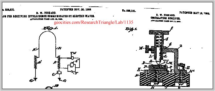
I think this letter, dated October 8, 1928 that I found in these Harvey Fletcher files at Brigum Young University in Provo Utah says it all. I quote from the letter, " He also took a lump of lead treated according to his process which he has invented and used it in place of the crystal, and got wonderful reception of radio - loud enough in fact, to operate a horn speaker of the type put out by RCA about 1923". End of Quote.
The first mention of the "Swedish Stone" was in the publication "Beyond the Light Rays" in 1931, two years after Murray 0. Hayes made the statement in this letter.
Murray 0. Hayes wrote this letter to a potential investor who sent a copy to Harvey Fletcher and asked his advice is he should invest in Moray’s invention.
Murray 0. Hayes was at the time of this letter an investor and an officer in the Moray Products Development Company. He goes on in this letter and other correspondence to state moray had made full disclosure to him. I quote further from this letter. " This machine has been operated in my presence so many times, under so many different conditions of weather and season that I am positively convinced that it is what its inventor claims it to be, and that its commercial adaptation is feasible. I believe that Mr. Moray has explained all to me without reservation, and I am sure that this is a revolutionary and echoic making invention". End of quote.
T. H. Moray himself in the fourth edition in 1960 says he found the "Swedish Stone" in a railroad car in Sweden in 1913.
Murray 0. Hayes in 1929 says Moray invented the "Swedish Stone". T. H. Moray in 1942 in the fifth edition is quoted as to never having been able to duplicate the "Swedish Stone" .
He found it, he invented it, but he could not duplicate it! What inconsistencies we have here!
My research has led me to believe Murray 0. Hayes was telling the truth in his description of the "Swedish Stone". It was in reality a lead alloy to which radioactive material has been added while molten and allowed to re crystalize.
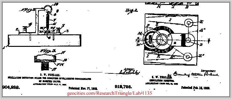
Before I continue with this scenario I would like to show you one particular patent that has some merit.
I have been in contact for almost a year now with a fellow researcher in Sweden who has been helping me follow this scenario. I first got reports of this from a friend in Utah and have had the blanks filled in from the researches done in Sweden.
This is the story I have been able to piece together over the past few years. While T. H. Moray was in Sweden between 1912 and 1913 he was a missionary for the Mormon Church. All Mormons must go on a two year mission, church rule. While on his rounds going door to door trying to convert people in the back woods of Sweden to the Mormon religion he met a particular amateur radio builder. From this person he acquired the infamous "Swedish Stone". This person would not tell anyone how he made it, but did say it contained lead and radioactive material. He would show people including Moray how it would amplify weak radio signals when placed in a crystal radio set. The crystal radio set he used was manufactured by the Erla company in Sweden.
Moray brought a piece of this material home and it was his ingenuity that used that simple little bit of amplification to generate usable electric power.
What happened to this person in Sweden? As best we can determine at this time he was killed in World War One which broke out shortly after Moray left Sweden and returned to America. The secret apparently died with him.
I will continue to work with my contact in Sweden and hope to have names, dates and places to offer as the final proof before my book is released, hopefully later this fall.
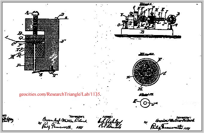
Now lets go back to this patent and see if we can figure out how to duplicate this material.
This type of material and the types in the patents will give some amplification. Not a whole lot but some. In one test I ran I used a particular alloy I had made and doped with uranium which gave me a 12.5 watt output when used in a Moray type of radio receiver. I ran this unit intermittently for several days with no degradation in output. My output was nowhere near the 650 watts of Moray but if I had a megawatt AM broadcast station nearby as he had maybe I could have gotten the 100 watts he had in the second generation device. Also had I used multiple stages maybe I could get the 650 watts he had in the second generation device.
Before going on to the next stage of the development of the Moray devices I want to give some insight to the testing and claims of this unit. Supposedly the Moray unit was capable of putting out 50,000 watts. Well it did put out that much in one test, the problem was how the test results were interpreted.
This is another letter from the Harvey Fletcher file. It documents the test in 1928 which the book says the unit had an output of over 50,000 watts. In the letter a test was conducted with the unit sealed in a trunk. During the test two light bulbs, one 100 watt bulb and a 10 watt bulb, were connected to the unit. This test ran for 83 hours and 34 minutes. After the test Moray connected a 575 watt flat iron and a 60 watt bulb to the unit to prove that more power could be drawn from the unit. Now if you take the 83 hours and 34 minutes and multiply by 635 watts you sure do get over 50,000 watts. The only problem is that is a total power not an instantaneous power as they would have
us believe. In actuality the unit only produced a continuos output of 110 watts during the test which gives a total of slightly less than 10,000 watts of total power production. One more time the truth was distorted to give a different perception. But to many investors this was enough to separate them and their money. The complete Harvey Fletcher files are full of letters from potential investors wanting to confirm the stories they had been told before investing their money. The files also contain Fletcher’s answers to them explaining that what said about the Moray device was being miss-represented. The files are full of Fletchers opinion of Moray and what he thought Moray had really done. Here are a few quotes. "it can not be investigated as long as Mr. Moray retains his present attitude." "In my judgment Mr. Moray is not a scientific man at all and if he has anything worth while it is by mere chance." if he has achieved something which is novel and useful it will be merely by accident rather than as the result of organised research." "recent developments have led me to question his sincerity." " I advised my friends not to invest any money" "Those who have tried to promote the invention have been double crossed by Moray just at the juncture when they needed his help to disclose the invention.’’
End of quotes. I strongly suggest any one interested in the true Moray read the Fletcher files, it gives an insight into the man and his research that has never been seen before. It also lends credibility to my long time theory that Moray did not know what he had or how it really worked and he was afraid to let anyone who could figure it out get too close because of his fear of them stealing it from him.
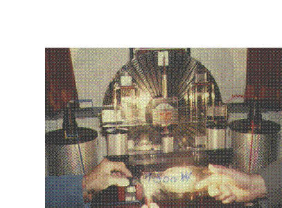
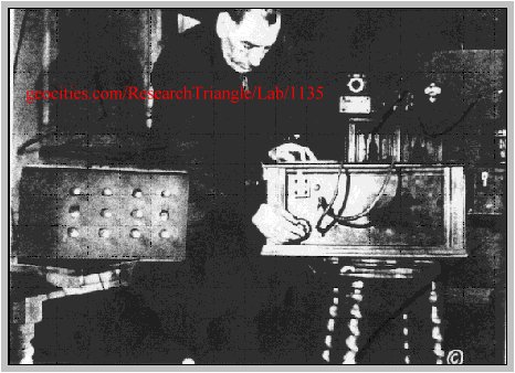
This is a picture of the fourth and final unit of T. H. Moray. In his research Moray came up with an acceptable type of alloy and a detector arrangement to allow him to build the device shown in this picture. By staging these detectors in series he found he could increase the voltage and current in each successive stage. This allowed him to build up to a voltage of approximately 250,000 volts and a current of approximately 12 milliamps. If you multiply this out using the formula of P=IE you will find this comes up to 3000 watts. In the picture we have 35 light bulbs and a fiat iron. The top six rows all contain 50 watt bulbs. The five bulbs in the bottom row consists of 100 watt bulbs. The flat iron which drew 575 watts is also plugged into an adapter in the bottom row. If we add up all of this wattage we come up with a total of 2875 watts. This sure is a long way from the 50,000 watts claimed as the output. However it must be remembered that this much power could only be drawn for short periods of time as prolonged runs would overheat and bum up the "Swedish Stone" or alloy as I prefer to call it. This device worked by the direct conversion of radioactive emanations to electricity and not from the conversion of some energy from space. The only energy from outside it needed was the small signal it got from a local radio station through the antenna. This signal was necessary only as a catalyst to both start and to sustain the conversion process. No form of cosmic radiation was either used or needed in any of the Moray devices. They operated by the direct conversion of alpha radiation to electricity with out going through a heat cycle as in modem reactors.
Before I move on to other free energy devices I would like to give you my conclusions on the Moray devices. Despite all of the dis-information and total lack of information put out by the Moray’s T. H. Moray really did have a working unit. It may not have put out as much power as claimed but it did put out power from very little input and thereby qualifies as a major step in the development of free energy. The distrust of T. H. Moray of everyone who tried to work with him kept T. H. Moray from fully developing this product and getting it to market.
Now let us back up to someone who showed more success and showed it earlier than T. H. Moray. This person was a man named Harry E. Perrigo.
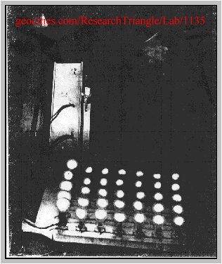
There is very little information published on his works even though he out performed T. H. Moray. As I stated earlier he predated and outperformed Moray by producing 4500 watts in 1922.
In Article we can see the antenna for input of RF energy, the two lead plates with the coil cores and coils. He stated the secret was in the cores plugged into the lead plates on which the coils were wound. These coil cores can be seen here in the center of the picture and consisted of a bundle of cut lengths of steel wire which were coated with a radioactive material. The steel wires also acted as the magnetic core for the coil of copper wire which was wound on it. The lead plates were only used for shielding against the radiation. The radioactive material emitted alpha particles which were captured by the copper wire and developed both voltage and current by being modulated with the incoming RF energy from the antenna. Any voltage and current output desired could be produced by changing the interconnections between the various coils. Again the direct conversion of radioactive emanations to electricity.
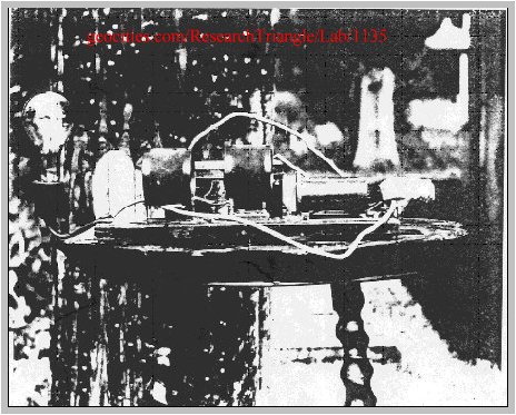
Now let us move on to theAlfred Hubbard device article.
The first picture shows Hubbard with his first device which produced 100 watts in 1919 and the second picture shows his last device powering a boat by driving a 35 horsepower motor by producing 26,000 watts in 1926.
This schematic diagram shows how the unit was constructed. Again we have steel cores impregnated with a radioactive material, Radium in this case, wound with copper wire, interconnected coils to give the desired output voltage and current desired and excited with an external source of AC current as a catalyst. Again we have the direct conversion of alpha radiation to voltage and current.
The best detailed explanation of theHubbard and the Perrigo. devices are found in the patent and these two books by Dr. Paul Brown since his device operates in the same manner as both of these devices.
The next device on our list is the devices of Lester J. Hendershot.

From the above schematic of the device. From this we can see a classic push pull oscillator circuit with the door bell circuit at the bottom setting the frequency and phase relationship between the push and pull circuits. Again there is very little constructive literature on this device. So where does the power to run this come from? Although Mark Hendershot,. admitedly denies that there was ever any radioactive material in his fathers device I have had my doubts for a long time.
We now move to the Testitaka free energy generator, from Switzerland which was first shown in the early 1980’s. This is a front view of the three kilowatt unit. I am sure most of you have seen the front of this unit but how many have seen the rear of this unit?
Here on the rear of the machine we see the heart and soul of the machine. The two tall silver cylinders are high voltage capacitors and the circular unit at the bottom and center is the high voltage distributor that furnishes the high voltage pulses to the sectors to drive the unit via the Poggendorif principle.
As you know, or maybe you did not know, the sectors of this modified Wimhurst generator are made of stainless steel. Both counter rotating wheels both pass through horseshoe magnets on both the left and right sides of the machine.
These magnets have coils wound on the center curvature of the horseshoe. So how does it?
Work? Again there is very little facts known about this unit however there are a lot of speculation about how it works. So here are my thoughts and deductions on how I think it work.
Additional Information on how the testakica may workHere we see a patent for a high voltage generator using radioactive materials. This is just one of the many patents in my book Patent Data Base showing how to use radioactive materials to make high voltage generators. If the two tall capacitors on the rear were radioactive high voltage generators we would have the high voltage needed to feed the distributor to power the unit. The high voltage generators in the patents can generate voltages for a single capacitor of over four million volts. These capacitors can be connected in series to produce as high of a voltage as you wish. The only limit to how high is the insulation used to prevent arcing.
Here we have a patent that shows that large amounts of power can be generated by generating high voltage with radioactive material. This patent shows a unit that can generate from 0.5 kilowatts to 500 kilowatts in the same unit just by changing the amount of radioactive material in the unit.
Now we have a way to make the unit rotate for free, so where do we get the output power? Remember the stainless steel segments and the horseshoe magnets with the coils wound on them? When these sectors rotate through the center of the horseshoe magnets the are not attracted or repelled because they are stainless steel. However they do disturb the magnet lines of force in the field of the magnet which is transferred to the coils on the magnets thus producing current without the nagging back drag effect of most magnetic generators. The problem is that the current produced is small in comparison to regular magnetic generators. However in this unit that does not present any problem. If you remember most Wimhurst can easily produce 100,000 volts. So if the output is three kilowatts and we have 100,000 volts the formula P=IE tell us we only need 30 milliamps of current. Easily produced with the setup in this unit. The glowing horizontal tube at the top and center of the unit is a tube filled with a mixture of helium and neon to act as an output voltage regulator to limit the output voltage to what ever voltage is desired.
Now to the final part of my presentation. Where do I think the increased power of the new super magnets come from? I will give you three guess and the first two do not count. RADIOACTIVE MATERIALS!! In the following charts I will show the naturally occurring radioactive isotopes of some of the materials used to make these super magnets.
Cerium. has only one isotope which accounts for 11.07 % of the naturally occurring material. We also see that it is an alpha emitter with an energy of 1.5 Mev.
We know that Neodymium has only one isotope which accounts for 23.85 % of the naturally occurring material . The alpha particle emitted has an energy of 1.8 Mev.
Samarium has three isotopes which account for a total of 40.04 % of the naturally occurring material . The energies of the alpha particles emitted are 2.24, 2.14 and 1.84 Mev.
It is evident that as the percentage and energy of the alpha particles increase so does the power of the magnetic material produced when incorporating this material into magnets. Another interesting property of these magnets is that once the material is compressed in the mould and before it is energised to make it magnetic a Geiger counter will register activity from the radioactive material. However once the material is energised and becomes a magnet absolutely no radiation can be detected. My theory is that the energy of the alpha particle is being converted to magnetic energy and thus increasing the magnetic power of the magnet as the percentage of radioactive material and or the energy of the alpha particle is increased.
I guess the next step is a logical one. My question and thereby the proof of my hypotheses would be to make a magnet using the ultimate of the easily obtainable high power alpha sources, Uranium. As you can see from this chart the isotope U238 accounts for 99.27 % of the naturally occurring material. The energy of the alpha particle emitted is a whooping 4.5 Mev over twice the energy and percentages we find in Samarium. This means, if my theory is correct, a magnet made with uranium should have at the minimum twice the magnet power of a magnet made with Samarium. As soon as I can arrange adequate funding I intend to try this out.
In conclusion I hope my talk today has been informative and not too boring. I have done my best to show the connections between free energy, increased energy and radioactive materials, alpha emitters in particular.
NB:
Some diagrams and photographs and text in this original presentation have not been reproduced due to size limitation and also if you have any questions or wish for the full version might I suggest you contract the author himself at the following website and email addresses
JOHN W. MORELAND, Ph. D.
AZTEC PUBLISHING
1251 SMITH THOMPSON ROAD
BETHPAGE TN. 37022-9110
PHONE 615-888-3428 FAX 618-888-2538
Additional Resources on subjects mentioned in this article
More specualtion on the Testakica


