
THE FREE ENERGY CIRCUIT CONNECTION for the serious inventor
After seeing the simple circuit as described by Dr Peter lindemann Dsc I was stuck by the similarity between the circuits that other free energy researchers claimed to have used in their inventions.
A possible answer to how the Testatika and Edwin Grays machines workThe basic concept as I understand it, is a high frequency high voltage low current rectified and then used to charge a bank of high value capacitors and then to discharge them in pulse mode for brief period of time, nano seconds in fact by, means of a high speed electronic switching circuit or mechanical device and a rectification method that will only allow the high voltage charge to flow in one direction .
The switching device could be a rotating spark gap as used by Nikola Tesla or some high speed electronic device, it is my belief that only glass tubes such as diodes or triode valves are really good at this and not transistors as they cannot handle the high voltage and high current produced in these devices without burning themselves out..
This type of design can produce a very high amperage current for a faction a second that can used to do some useful work if properly harnessed.
A point to remember is that Paul Baumann built his first device in prison and as such did not have access to exotic materials as is often described in other theories of how the Testakica was said to have worked.
One would conclude from this, that as such, that the home experimenter should also be able to build such a device from material from around the house
REMEMBER THE KISS PRINCIPLE AND KEEP IT SIMPLE STUPID.
Getting the high voltage to start with.
There are two main types of methods that I am aware of are they are.
STEP UP VOLTAGE transformer
As used by Edwin Gray in his invention the charging circuit is basically a 12 volt battery being driven by vibrating relays to pulse the power through a step up transformer to raise voltage from 12 volt to approx 3000 volts this then, is rectified and used to charge a bank of capacitors.
This bank of capacitors is then discharged for a nano seconds period into special design tube which seems nothing than a copper rod a spark gap some carbon and a series of concentric rings around the spark gap and the resulting power collected on those rings is then fed to the earth via a air induction transformer or to the positive terminal of the charging batteries .
The power appearing at secondary of this air induction transformer is then used to power the motoring coils of the specially design motor.
High Voltage Induction Coil
Another method used in early X-ray machine and also Marconi in his first radio transmission across the Atlantic ocean was the induction coil basically a two coils wound on a metal rod a small number of primary windings in heavier gauge wire and large number of finer gauge winding ,basically a step up transformer using the primary magnetic field to operate a switch that controls the power to the primary winding.
This causes the magnetic field in the primary coil to build up and down which then causes by induction an alternating high voltage output in the secondary coil.(most likely a square wave)
See circuit above.
Electrostatic generation of high Potential.
The People at the Swiss Community of Merithnita see to be using a wimshurst machine to generate the high voltage needed to run their free energy device.
The device was a popular means to generate high voltage in the late 19 century and early 20 century .
It role was at some stage used to provide the high voltage needed for early x-ray machines in hospitals but today is usually superceded by the modern electronic version or the Van de Graaf machine in modern physics laboratories today.
The wimshurst design is basically two counter rotating disks of a plastic or glass material upon which are place metal foil sections separated from each other.
This device’s discs are spun in opposing directions by means of a belt either hand driven or motor driven.
Brushes mounted at various points near the disk’s metal plates but not touching the disk collect the charge and usually then conduct it to a capacitor storage position or discharge the built up charge through a spark gap.
Another device is called a Dirod
This a flat circular plastic disk upon which have been glued several conductive metal rod’s mounted in radial positions around the disk.
This disk is spun by means of a hand crank
Four pickup positions mounted along side the spinning rods pick up the charge through conductive foil or conductive plastic as used in computer electronic parts packaging and then either discharge the high voltage buildup through a spark gap or charge a capacitor bank.
It is my conclusion that the Single Swiss disk version of the Testatika makes use of the Dirod principle in it’s design of the smaller version of the single disk Testatika machine to generate the high voltage potential.
I refer to the circuit diagram as reproduced below which consists of transformer which raises the voltage to several thousand volts which charges a capacitor bank to several thousand volts and then discharges it across a spark gap.
In the original patent drawing as produced by Stan Meyers the transformer appears to be an automotive step up transformer but as friend has indicated to me that the coil would be unable to handle the frequencies needed to make this circuit perform ,he however has removed the center core material and has found he is able to use it at high frequencies.
My friend is using a waveform generator (square wave ) to drive an electronic high voltage car ignition system as used in modern automobiles ,I think he had made it from kit.
I saw him using this setup to drive high voltage sparks across some ½ inch carbon rods and it seemed rather impressive.
He used a car battery as the power source.
The Stan Meyers circuit
This circuit appears to charge a water cell with a high voltage source , Stan Meyers claims he had to resonate the water cell with a high voltage charge.
The question of him resonating the cell would appear to be incorrect as he has added a diode in the output circuit this would in fact making it a DC pulsating circuit.
This circuit diagram would appear to be a simple high voltage charging circuit and the water cell is in fact acting like capacitor.
The choke coils in the circuit and one seems to be adjustable maybe to prevent the premature voltage breakdowns due to short high voltage spikes that need to be avoided.
Other’s more in the know of the function of such circuit could perhaps fill me and others in more,
When the voltage reaches a point where the dielectric breakdowns ,the voltage short circuits causing a high current surge for a brief period time causing the water to break down into it gas combinations by means of electrolysis.
A friend of mine has used carbon rods in some high voltage experiments and has found that they seem to work better than stainless steel ones which seem to contaminate the water cell, he has found that by using carbon welding rods the contaminating action does not seem to occur.
He has also tried the circuit with out the diode and found that he could get any gas to form.
He has limited success using two carbon rods in the container.
I feel however that if you use a single carbon rod in the center of metal water containment vessel and use it also as the other terminal it might be possible to get greater output of gases.
Stanley Meyer electrical generator US Patent:4,613,304Stan Meyer Hydrogen gas burner US Patent: 4,421,474
Stan Meyer System for the controlled intermixing of a volatile hydrogen gas with oxygen
Stanley Meyer eye witness report
Method for the production of a fuel gas US Patent: 4,936,961
System for flame start-up/shut-down for a hydrogen gas mixture burner
Controlled process for the production of thermal energy from gases and apparatus
Stan Meyer Gas generator voltage control circuit US Patent: 4,798,661
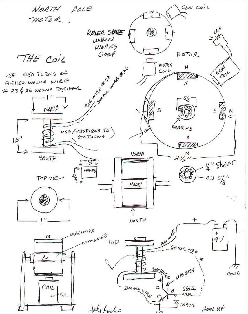
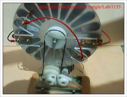
THE POWER WHEEL OF CALVIN BAHLMANN
Calvin has built a power wheel using NIB magnets and special coils.
The plexiglass wheel is cover with magnets which revolve at a constant rpm ,the coils only gather voltage but charge a capacitor bank which discharge at predetermined ratio to the driving coils.
It’s certainly impressive to see his large unit running on a small nine volt battery and not missing a beat.
The device was on show recently at Bruce Perrault inventors weekend and I would certainly recommend you get yourself a copy of the video.
nuenergy.orgJOHN BEDINI
John Bedini has been doing something with similar with coils and capacitor banks using trigger swiches mounted on additional rotating smaller wheel to run his machines.
This apparently he has done for years but largely ignored ,but has had some success lately with a student winning a science fair award with a variation of his idea.
The device is basically a roller to which four magnet have been attached and moving over a magnet pickup coil and a drive coil on the same former.
The device is not self starting but once spun as I understand it will continue to run with the magnetic field produced in the pickup coil by the spinning magnets switching the drive circuit transistor and acting as switch to pulse the current need to fire the motive coil.See more at below .I have tried to reproduce the device myself ,but with little success ,but have no doubts that John Bedini ideas works and the trouble is at my end not his.
Experiments with a Kromrey and Brandt converter built by John Bedini
John Bedini motor diagrams and Lab notes
John Bedini energy machine pictures
The Hamel magnetic gate as built by John Bedini
John Bedini has been granted a patent on his device hopefully something positive comes of this.
Ed Gray Circuit
This too seems to a circuit with similarities with the others
Here a bank of batteries is used to create a high voltage and is transformed by means of an air core transformer then rectified and then used to charge a bank of capacitors
The capacitors then is in turn discharged through spark gap and for a brief period of time by some means mechanical or other means and into a special tube and spark gap rod component that appears to consist of some carbon and other metals surrounded by a grid that some say collects the high charge resulting in the buildup of voltage in the spark gap conductors prior the discharge from the area surrounding the spark gap.
This then claimed excess energy is collected from the surrounding cylinders and then transformed to do useful work.
Re discovery of the E.V. Gray Electric motor
The Edwin Gray Pulsed Capacitor Discharge Electric Engine
A possible answer to how the Testatika and Edwin Grays machines work
The Testakica Machine
I have had an interest in these machine for some time ,but never really understood how it worked but knew it had to be based on something simple as the Inventor Paul Buamann built his first unit in prison and would have not been able resource exotic materials as have claimed by to be the method by which the device works.
It would seem to me be based around some of the concepts as discovered Edwin Gray.
The spinning wimshurst machine twin disc’s creates the high voltage source need to charge the capacitor bank which are then discharged at a precise time period ,I believe the rectification mentioned in video refers the stopping a reverse current and voltage flow as is the case in Edwin Gray Device
This is how I think the large machine works although no one apart from Merintnita organization really knows the details and with the death of Paul Bahmann the secret may be lost forever.
I believe the machine actually collects and stores high voltage collected from the spinning disk.
The video I have and have seen says the the device is started by spinning the disk by hand. And the becomes self running.
The video also says the device needs to operate a given speed and apparently slowly as well.
The device rectifies the high voltage produced and this wpould be needed if indeed the device is using pulsing high voltage discharges.
Making your own electrostatic machine
There appears to be more pickup points than is really needed to capture the high voltage ( a wimshurst machine really only needs only eight collecting positions on the disk to function.
I suspect the other brush positions are a method to feed some of the high voltage produced from the cans area to enable it to be used as a propelling force which is possible if the disc’s are properly balanced,
A simple high voltage on motor powered from your TV screen
What it does not say that there must be a firing control for the high voltage, possibility a version of a rotating spark gap, I suspect this is controlled by means somewhere on the disk either directly or by means of the belt drive that appears to be on the machine as a speed control function.
Theres a Pal video that’s out there that was produced approximately 20 years ago now that gives a detailed account of the metherinthina community and show the testakica machine working.
I am also aware that some web sites on the net also have some video clips showing the machine working as well these have been taken from the video..
John Bedini on his machine uses a separate disk driven with belt to main revolving wheel with a contact point on it to fire the pulse for his machine maybe it something similar for the Testakica.
I notice on The Testakica machine video what appears to be a relay or pickup coil opposite a revolving wheel which needs some explaning as to what it function could perform.
I agree with others that now say the big cans perform a function similar to the Ed Gray Capture tube but I think with a slight difference.
I believe there could be a rotating spark gap controlling the pulse delivered to the tube and that there is no spark gap as such in the capture tube.
I noticed too that Ed Gray used a piece of carbon in his device and called it a carbon resistor, I have my doubts as to the value of the resistance value.
I have noticed too that several other experimenter using carbon components in there types of devices are getting better results than expected as well
Apparently some capacitor manufactures are using carbon plate’s area’s to manufacture superior capacitors so carbon itself could be something to examine closely.
Telsa is also said that carbon was excellent at capturing the energy he was experimenting with, so I would suggest that there is a whole carbon rod running the entire inside length of the large capture cans shown in front of the testakica in most photographs I have seen of the device.
This a circuit as I see the testakica now connected although as I have said before only that Swiss community really know for sure and their not saying anything..
The People Mover
Some months ago now there appear on TV a motor scooter that was said to be the IT or Ginger that people have appeared curious about for some time.
I have heard it can run at 12mph for 24hrs on a few cents of electricity,I not aware of any batteries that can provided this much power for this amount time ,So could this be the first of free energy devices on the market and the inventor seem to indicate that there more come.
