|
Back-Engineered Methernitha
That the Swiss Methernitha group's Testatika machine is thought
to be based on a Wimshurst electrostatic generator, is only a sparse
approximation of the truth – of the great multitude of electrostatic
influence machines developed around the 1900's it more closely
follows the charge-separation-and-collection system used by the 1898
Pidgeon machine [note
1] for its electrical circuit.
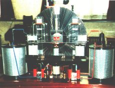
Its 50-per-disc steel grilles or 'gitter-grilles' are plainly
unique to the Methernitha (see fig.1) but
in principle follow on from previous research and patents for
corrugated sectors which were found to be more efficient charge
carriers [note
2] than flat ones, and from a similar example in more recent
times of aluminium rods extending out like wheel spokes from an
insulating hub of perspex [note
3].
Another unique function of these perforated grilles attached to
the discs is how they induce charge from the rotating discs onto the
special collecting pads, or 'tasten'
antennae keys (which are also perforated – so as to more readily
pick up charge); for in a Wimshurst you had conductive brushes or
rails of sharp points which actually touched the discs or were
placed very close to them, but in the Methernitha the charge has to
be made to traverse a parallel air-gap to the pads and for this
purpose the metal gitter-grilles are so designed to create miniature
eddy-currents of charged air which circulate in and out of the
perforated metal's surface charges, and are more easily bounced out
to the collecting pads. This process is categorised as VARIABLE
CAPACITANCE electrostatic generation.
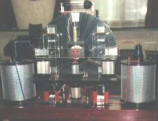
Careful note needs to be made of how the Methernitha uses its
basically Pidgeon setup with regard to its neutralising rods (that
equalise and stabilise the opposite charges – see fig.2), and
how charges are picked up from one area and accumulated at others,
so that the polarities of charge are distributed correctly to
specific areas on both discs [note
4].
And although there have been some fanciful claims, or
misinformation, that it uses all sorts of radioactive materials to
achieve its pulsed output I most strongly believe that the auxiliary
electromagnetic circuit, that wraps itself around the rotating
discs, portrays a simple electronic approach; afterall, who would
use radium radioactive emission alongside leyden jar capacitors !
Indeed, the more you look into certain elements of its construction
the more they point to three main eras of electronics development,
the 1900's, the 1920's and the 1950/60's. The authentic Methernitha
was designed and developed by purists who believed they had
discovered a previously unknown electronic phenomenon, but they
wanted to keep an integrity to the early pioneering days of the
Pidgeon, Wimshurst and Holtz electrostatic machinery; they would not
use such modern devices as transistors or IC chips (more's the pity)
– but they do use some pretty uncommon electronic engineering in
their circuit [note
5].
Obviously, the electronics are in two parts; one – the
electrostatic generator and its particular technologies of how to
direct what charge where, and two – the very unique auxiliary electromagnetic
circuit of inductances, capacitances and rectification that
mobilises that 'static' electricity. To understand how they convert
static energy into an electromotive force you would do well to go
back to the earliest years of radio. From the pages of spark radio
you soon appreciate just how important oscillation circuits and
their valve rectifiers were, and moreover, how difficult it proved
to engineer them. For although radio transmitters and receivers from
the 1900's used resonating circuits their oscillations were
controlled by sparks between two contacts and, of course, they were
relatively inefficient. Not until the 1920's did the first electric
current oscillations become an observable, controlled, phenomenon
when someone coupled a rectifier valve, a capacitor, and a resistor
together [note
6]. The early 1920's also saw the best era of experimentation
and invention for novel devices that turned static energy into
useable electromagnetic energy; it was in a 1921 patent that we see
a German physicist Hermann Plauson describe in great detail his
methods to convert static power, not only from rotary influence
machines but also from balloons collecting atmospheric electricity
up in the sky; and by using thermionic rectifiers, leyden jar
capacitors and inductor coils he proposed a free-energy network that
was to power the whole of Germany [note
7] ! The thermionic rectifier valve heralded a new era for radio
and high voltage physics, and as it was then subjected to such a
broad array of experiments and modifications to improve its
efficiency so it paved the way for all sorts of new avenues in
electronics. Indeed, with such a technical catalogue of similarities
with what we see in the available photographs of Testatika it can be
assumed without doubt that the horizontal glass tube which sits on
top of the Methernitha machines is exactly what a home-made vacuum
thermionic rectifying valve would look like; with its internal anode
mesh-plate, surrounded by a coiled copper grid, fed by a glowing
(heated) cathode wire running horizontally across its centre and
capped by two black end-pieces, which are too big and bulbous to be
mere end-caps and must surely be black rubber vacuum seals to seal
the glass tube and the input/output wires [note
8].
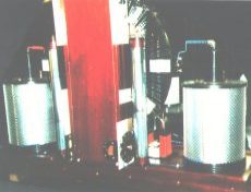
With such a rectifier, some induction coils, and some leyden jar
capacitors you have a circuit that oscillates, and that's what has
to happen with a Methernitha, the electromagnetic circuit has to
oscillate for it to work, and then the oscillations have to be
rectified (or even modulated) so that the resulting single-pole
pulses can be channeled through the big cans, which are basically
high-efficiency transformers, and outputted as reduced voltage
higher current DC pulses (see fig.3).
The precise components used to oscillate the primary oscillating
circuit are, I believe, not to be seen in any of the available
photographs, but there are various hints for their approximate
whereabouts on the machine. Firstly, according to electronic design
there should be a capacitor and coil configuration in close
proximity to the rectifier. Well, from the picture "3KWREAR" can be
seen the two long upright tubes which, according to those who have
seen them first-hand, comprise a spirally turned aluminium strip
(which indicates they are chokes [note
9]) inside a glass tube, inside the same sort of outer shielding
that the big cans have (which indicates they are electrostatic
shields), inside yet another glass tube, and are terminated at the
top with a brass connecting rod which does a right-angled turn and
passes into the side of the tower – but only two-thirds up the
height of the tower. These two assemblies must form a connection to
the rectifier, because the rectifier is at the top of the tower, so
why don't these electrostatically sensitive tubes extend all the way
up to it ? Again, from the photographs of the rear and front of the
Methernithas there is a wire that comes out of the tower's side wall
at about 4 inches above the upright's brass terminals and this wire
then passes through a short black tube and on to the rectifier
valve. This, of course, would happen on both sides of the tower,
enabling a connection to both ends of the rectifier. But why have
this 4 inch gap of connections at the top of the tower ? Something
is placed inside the top of the tower in this intermediate space
which is very necessary to the circuit, and I think it must be the
location of the capacitor/inductor configuration to oscillate the
circuit. This (fig.4) is
how I would see the inside of the top of the towers [note
10].
I've seen some of the patented inventions that rotate discs - by
using magnets (ie H.Rosenberg's permanent magnet excited rotational
machine, US patent 3,411,027), and by utilising inscribed metalised
discs (US patent 3,239,705 for instance), but there simply isn't
enough room for these to be located in the Methernitha disc setup –
also, you don't want to interfere with the ES fields that zip around
the revolving discs: From the reports
of those who have seen the small machines working it
appears their discs were rotated by small DC electric motors after
they were hand-started, some re-wound with thinner wire (to
presumably increase their torque) and powered directly from the
discs' generated electricity – but I have also seen how two discs
can continue to rotate simply by careful placement of curved
electrodes [note
11] which would act on the charges on the discs – like the 3kw
Testatica Distatica generators.
After reading through the many early accounts of electrostatic
rotary machines, and some of the more recent ones, you can't help
but be puzzled by the Methernitha's incredibly low rotational speed
of just 60 rpm (and in the 1999 engineers report as low as…15 rpm
!). Most other early experimenters boasted up to 3000 rpm, J.G.Trump
in his work on high voltage generation in space [note
12] spun his rotary machine at 10,000 rpm (to produce 433 Watts
at 24 KV no less). One reason for this low speed might be to do with
the close proximity of the 50 lamellas (gitter-grilles) on the discs
at their inner ends, they are very close together, I think too
close. Air, normally an insulator, breaks down and conducts at
around 25-35 KV (this figure has been fairly constant from day-one
of electrostatic machine experiments right through to the present
day – because air has a breakdown field strength of 3x10⁶
volts/metre) and short-circuits the circuit. I feel that
because this design of grilles is prone to short-circuiting at high
voltages the Methernitha people have limited their rotational speed
so as to ensure a low operating voltage – of what I'd guesstimate to
be only 12 to 24KV.
But, is this a waste of extra potential ? Not necessarily…For I
don't think that the main power output comes solely from what the
two contra-rotating discs supply.
There is, I believe, a far more important power generator…the
electron cascade generator, and the Methernitha has two of
them, held inside the two horseshoe magnets, and providing the
circuits to the magnets are made to oscillate at the right frequency
at a high enough voltage then these metalised-perspex laminated
blocks can enmass A MUCH LARGER AMOUNT OF ELECTRICITY THAN WHAT IS
PUT INTO THEM.
This, perhaps, is the previously unknown electronic phenomenon
that the Methernitha group have so zealously been trying to protect
against unscrupulous entrepreneurs. But I would say that this
copious supply of free energy is already known to the world - it is
not readily available - and its principles are not fully understood,
as yet, but it is known about.
As the descriptions say (on the Testatika
website), between the horseshoe magnet legs are four blocks of
transparent 'plexiglass' type material alternated with copper and
aluminium plates (that may or may not be perforated), in the
sequence c-p-a-c-p-a-c-p-a-c-p-a (also see fig.6). And
according to the Linden
Experiment, where Paul Baumann induces a resonance of about
80-140 MHz in a coiled horseshoe and then has an
aluminium-insulator-copper block moved between the horseshoe legs, a
voltage could be taken off the plates of the block which measured
700 volts (DC presumably) [note
13]. This incredible phenomenon has never been replicated by any
'outside researcher', and is said to be the basis by which the
Methernitha machine could be understood how to work [the clue,
possibly, to this principle may be variable-capacitance
and dielectric-absorpsion].
But what, I hear you say, is an electron cascade... Well,
it was only by chance, very recently, that I happened to listen to
an audio tape by a Dr. Flanagan about crystal water; when I switched
the tape over after the end of side one Dr. Flanagan then began
talking about an electronic configuration that applied a high
frequency, high voltage alternating field across an insulator – that
created what he called an electron
cascade effect – Yes, I thought, here is the answer to the
Methernitha Machine.
The electron cascade or avalanche effect is where air molecules
are accelerated to the device at such a high velocity that they
collide with other molecules and atoms in the air to liberate new
electrons which in turn also collide and liberate even more 'free
electrons' from other air molecules (see fig.5), all
of which become accelerated by the electric field, and an avalanche
of electron-multiplications progresses throughout the whole
immediate environment [note
14]. It's a chain reaction, and an entirely safe one, it happens
in a more ferocious way in lightning strikes, and is a natural
phenomenon. And, as in this case, the environment actually becomes
part of the circuit [note
15] because the process is actually negatively-ionising the air
surrounding the Methernitha machines, and that is why those who have
been near these generators when working say the air around about
them is cool and fresh [note
16].
In view of the fact that it's designers have chosen to wind
insulated wire (which may be bifilar [note
17]) around the horseshoe metal [note
18], it would be very possible to draw the extra electric
current produced directly from the electron cascade blocks, with
suitable connections that might lead downward into the wooden base
(where it is believed that an alternate layering of perforated metal
plates and insulating plates - making up a large high-voltage
storage capacitor - is located). This power could then be discharged
as a pulsed output of high wattage, especially if configured as a
Pulse Forming Network [note
18].
The two big cans at the side, are probably not highly technical
(see fig.7), once
the fundamental formula has been decided upon all models of a
testatika generator would follow a similar construction process. The
written descriptions are a little contradictory but they seem to
suggest a central input rod, or tube, connecting at the bottom of
the cans to a stack of inter-linked pancake coils, that are wound
secondary-outside primary-inside, fitted around a core of 6 hollow
donut-ring magnets stacked in such a way with plastic spacers as to
allow air gaps between them, and then finally the output of each can
is a connection from the top coil of the secondaries of the pancake
coils to a brass ring around the centre of the black plastic top lid
– and from the photographs can be seen a large diameter wire or tube
[note
19] connecting that polarity's output terminal to the top lid's
brass ring via a brass screw terminal. I would suggest that the ring
magnets (of anistropic ferrite perhaps) are gapped in this way to
prevent the magnetic flux fields of the pancake primaries co-joining
as one sprawling field, because it would be more advantageous, and
safer, to have each separate pancake's magnetic flux cut it's own
adjoining secondary coil, and divide the secondary output voltage
into smaller amounts of potential, thus depending less on
complicated insulating procedures that accompany high voltage single
primary / single secondary transformers.
The use of aluminium mesh and solid copper sheeting is commonly
used in electronic construction; the outer aluminium mesh cylinder
would be used to shield stray electrostatic charges, and the solid
copper cylinder is to shield the large amount of stray
electromagnetic fields produced by the transforming process from
high voltage/low current to lower voltage/higher current [note
20], obviously they don't want field contamination taking place
between the sensitive electrostatic generator and the transformers.
In the red wired can the transformer is wired to output negative,
and the blue wired can's transformer is wired to output positive
polarity. Special note should be made of a similar arrangement
devised by Van de Graaff in his 'High Voltage Electromagnetic
Charged-Particle Accelerator Apparatus Having an Insulating Magnetic
Core' [note
21] with respect to magnetic reluctance gaps.
Whilst it has been said that the clear perspex disc was
designated the 'cloud' disc, and the (rear) dark disc the 'ground'
disc I would think this relates to different types of acrylics or
plastics that might become charged to different polarities, as in
the triboelectric series, where frictional charging of different
plastics - and then bringing them close together, might cause
donation or acceptance from one to the other; I would think from the
above that cloud represents a donator (positive charge) and that
ground must mean an acceptor (negative charge). Has anyone tried the
combination of a teflon disc (extremely negative charge) with a
glass disc (highly positive charge) ?
Or doped discs perhaps [note
22] ?
|

