
|
DIELECTRIC ABSORPTION BLOCKS versus ELECTRET BLOCKS
The reason why I believe that the TestatikaÆs horseshoe blocks are not ELECTRETS is that when you look at a similar configuration of blocks used in each top corner of Methernitha's Tini machine (see Tini video 995 kb (This may not work on some computers) this machineÆs blocks give more of an indication that they are used as electron cascade generators to increase the amount of available electrons in the surrounding air that the generators can collect from, and I believe they are used on the Testatika in a similar way.
But, there are certain advantages to having electrets squeezed between the feet of the horseshoes as we shall see below. What, though, is an ELECTRETģ
How to make an ELECTRETģ There are two sets of instructions on how to make an electret that I know of but IÆm sure there are more, one is the original paper by the Japanese physicist M. Eguchi N3, and the other is by C.L. Strong published in Scientific American N4. But a word of warning, in making electrets proper precautions are important; the process can be hazardous especially when the dielectric material is melted to its liquid form, for it looses its insulation resistance, and then the high tension electrizing process can become unpredictable and even explosive. The trick is to heat the plastic blocks until they are soft and then take the heat away (with ample experimentation first to observe how the plastic reacts). DIELECTRIC ABSORPTION is almost exactly the same although it is not so permanent an effect as that which the electret process produces. From the early days of electronics when research into insulators and dielectrics was almost as important as research into conductors, it was noted that dielectrics exhibited Æelastic stressÆ whereupon they would absorb amounts of electricity into their structure. This ÆmysteryÆ was subjected to many theories and much experimentation during the 1800Æs but it was James C. Maxwell N5 who came up with a mathematical formulae for it and the explanation that it resulted from charge accumulations on the interfaces separating regions of different components that make up the dielectric material itself.
The HORSESHOES and why they are thereģ One problem in a Testatika type electric circuit is that there has to be sufficient isolation of the rotating discsÆ electrostatic field transfer system otherwise the whole thing will grind to a halt in a matter of seconds. Electrostatic influence machines do have a tendency to die if their charges are wrongly transferred (or not properly neutralised etc), and provision against this is very evident in the circuit assembly and connections shown in the photographs taken of the Testatikas (see circuit diagram).
Firstly there is a conductive break in the form of capacitor C1 (and for the return section C2), which will only be crossed by an alternating (or pulsed) current; and secondly there is a conductive break by the horseshoe coil windings (see fig.4), which are mutually coupled to eachother through induction (through the iron or mumetal of the horseshoe) but are not directly connected and will, again, only pass an alternating (or pulsed) current between them. So, while these two factors provide the isolation needed, at the same time they ensure that an alternating (or pulsed) current can pass between the electrostatic generator and the oscillating, rectifying, and transforming parts of the circuit.
But here, possibly, between the feet of the horseshoes are the main
reasons for using electrets instead of plain uncharged plastic blocks.
I suppose it would also make sense, while providing 'electrodes' for these electret blocks, as in the form of metal plates, that it would be advantageous to choose two such different metals so that when they touched they would pass current more easily in one direction than in the other. When the two are linked aluminium is positive while copper is negative - but it would be even better to use a zinc / copper combination (see Horseshoe Magnets page) and moreover, zinc more readily gives off electrons from its surface.
NOTES: N2 - See "Electrostatics ¢ And its Applications" by A.D. Moore (1973) is a very well researched book on electrets (p122 ¢ 130) and electrostatic machines; "Handbook of Electrostatic Processes" by Jen-Shih Chang (1995) pp509 on electrets. N3 - The first person to make an electret was Mototaro Eguchi, see his "On the Permanent Electret" paper in "Philosophical Magazine" Vol 49 (1925) pp178. N4 - "How to Make an Electret" by C.L. Strong in "Scientific American" Vol 203 (Nov 1960) p202 ¢ 210 is a practical description of how to make an electret using carnauba wax. N5 - "A Treatise on Electricity and Magnetism" by James C. Maxwell Vol 1 (1881) # 325 ¢ 334. And see above for A.D. Moore (p122). N6 - See "Dielectrics" by P.J. Harrop (1972) p71 for dielectric absorption. Doping the dielectric with, for instance, paramagnetic particles will increase the amount of, and surface area of, the interfaces; which is one reason why their inclusion in a dielectric increases the ionising effect. But see the Patrick Flanagan Electron Field Generator page too.
|
All articles in this series copied with permission from Paul E. Potters excellent website
check out the webmasters original article on the swiss ml
Some interesting comments and ideas on the Free energy machine Swiss ML or Testatika Thestica Distakica
I have an Australain Pal format copy only of this video
email me for pricing details Australian residents only

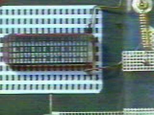 On the Tini there are three such assemblies of blocks of
layered plastic (one on each top corner and one at bottom-center), they
look as if they comprise of four or five clear plastic blocks stacked upon
eachother, separated by thin metal sheets, and the whole assembly is then
capped top and bottom by a flat metal plate to which a wire connection is
made, which leads off to another part of the machine (see frame 31 on the
left). On the Tini generators these block assemblies, especially the top
corner ones, face outward to open unrestricted space and are ideally
placed to draw to them free electrons from the air. All that is needed
then for the plastic blocks N1 to create the electron cascades,
or avalanches, is an alternating voltage which is readily supplied by the
oscillating circuit of the Tini generator (see Electron Cascade and
Electron Field Generator pages).
On the Tini there are three such assemblies of blocks of
layered plastic (one on each top corner and one at bottom-center), they
look as if they comprise of four or five clear plastic blocks stacked upon
eachother, separated by thin metal sheets, and the whole assembly is then
capped top and bottom by a flat metal plate to which a wire connection is
made, which leads off to another part of the machine (see frame 31 on the
left). On the Tini generators these block assemblies, especially the top
corner ones, face outward to open unrestricted space and are ideally
placed to draw to them free electrons from the air. All that is needed
then for the plastic blocks N1 to create the electron cascades,
or avalanches, is an alternating voltage which is readily supplied by the
oscillating circuit of the Tini generator (see Electron Cascade and
Electron Field Generator pages). Basically its an insulator which has been polarised to retain
an electric charge (likening it somewhat to how a permanent magnet holds
magnetism) (see fig.2). The process of making an electret involves heating
up a plastic material, applying a high tension electric field across itÆs
two faces, and letting the plastic cool down (and solidifying again) only
removing the high tension electric connection after the plastic has
solidified. The high tension electric field polarises and orientates the
molecular interfaces within the plastic (dielectric) and because the
material is soft (or fluid) they readily align to the direction of the
electric field; thatÆs why the high tension has to be continued until the
plastic has cooled down and solidified to lock the molecules in place.
After the plastic has solidified it exhibits an electrical potential
difference N2.
Basically its an insulator which has been polarised to retain
an electric charge (likening it somewhat to how a permanent magnet holds
magnetism) (see fig.2). The process of making an electret involves heating
up a plastic material, applying a high tension electric field across itÆs
two faces, and letting the plastic cool down (and solidifying again) only
removing the high tension electric connection after the plastic has
solidified. The high tension electric field polarises and orientates the
molecular interfaces within the plastic (dielectric) and because the
material is soft (or fluid) they readily align to the direction of the
electric field; thatÆs why the high tension has to be continued until the
plastic has cooled down and solidified to lock the molecules in place.
After the plastic has solidified it exhibits an electrical potential
difference N2. This Æinterface polarisationÆ (as it is now called) is slow to
react in a reversing electric field and this can be an advantage,
especially if the effect is magnified N6, as IÆm sure it has
been and then utilised ingeniously within the circuit of the Testatika
generator. For when each dielectric block has a current applied to it, it
will polarise its structure of molecular interfaces with positive and
negative charges (see fig.3), but when the applied current is reduced to
nothing the positive charges tend to move so slowly that for all intents
and purposes they remain stuck, and so when the next ÆpulseÆ of electric
charge comes in it compounds upon the previous unmoved charges, and so on
and so forth, hence the accumulative effect which carries on pumping more
and more electric charge until the blocks become saturated. Once this
occurs, and the alternating field is continued there is formed a highly
mobile space-charge of electrons around the outer surface of the
dielectric blocks, the mobility of which then triggers off the electron
avalanche effect where, as Flanagan has evidenced, it accelerates the
electrons in the air toward the dielectric blocks to such a high speed
that they collide with other air molecules to knock off even more
electrons. Hence they create a local ionisation of the surrounding
air.
This Æinterface polarisationÆ (as it is now called) is slow to
react in a reversing electric field and this can be an advantage,
especially if the effect is magnified N6, as IÆm sure it has
been and then utilised ingeniously within the circuit of the Testatika
generator. For when each dielectric block has a current applied to it, it
will polarise its structure of molecular interfaces with positive and
negative charges (see fig.3), but when the applied current is reduced to
nothing the positive charges tend to move so slowly that for all intents
and purposes they remain stuck, and so when the next ÆpulseÆ of electric
charge comes in it compounds upon the previous unmoved charges, and so on
and so forth, hence the accumulative effect which carries on pumping more
and more electric charge until the blocks become saturated. Once this
occurs, and the alternating field is continued there is formed a highly
mobile space-charge of electrons around the outer surface of the
dielectric blocks, the mobility of which then triggers off the electron
avalanche effect where, as Flanagan has evidenced, it accelerates the
electrons in the air toward the dielectric blocks to such a high speed
that they collide with other air molecules to knock off even more
electrons. Hence they create a local ionisation of the surrounding
air. This isolation can be achieved usually by one of two ways,
either by capacitive couplings, or by inductive couplings in the Testatika
it uses BOTH !
This isolation can be achieved usually by one of two ways,
either by capacitive couplings, or by inductive couplings in the Testatika
it uses BOTH !  It should also be noted that there is another reason for the
horseshoe magnets being placed where they are with, as you will have no
doubt noticed, two coil windings of the same number of turns (so they
cannot be used as transformers). For they are correctly placed to act also
as mutually-coupled iron-cored inductors, to act as chokes to compliment
the UPR (upright) chokes situated to each side of the back column, on the
way to the rectifier, this is to inhibit the current flow so as to prevent
current being unnecessarily discharged in the rectifying
process.
It should also be noted that there is another reason for the
horseshoe magnets being placed where they are with, as you will have no
doubt noticed, two coil windings of the same number of turns (so they
cannot be used as transformers). For they are correctly placed to act also
as mutually-coupled iron-cored inductors, to act as chokes to compliment
the UPR (upright) chokes situated to each side of the back column, on the
way to the rectifier, this is to inhibit the current flow so as to prevent
current being unnecessarily discharged in the rectifying
process. One - the four electrets in each horseshoe
could be connected, all in the same direction, just as a one-way diode to
allow one-way current flow (ie HP1 to HS1 toward the
rectifier; and rectifier to HP2 to HS2 and back to
the generator): or Two, which is more likely, that the electrets
are placed inside the horseshoe feet in a full-wave rectifier
configuration (see fig.6) so as to allow conduction of both POSITIVE and
NEGATIVE pulses to be directed into an auxiliary part of the circuit,
namely the base storage capacitor. ECG1 (EL1)
transferring charge to one terminal of the base capacitor and
ECG2 (EL2) transferring the opposite polarity to its
other terminal so providing an accumulation of (DC) charge for its output
terminals (see diagram below).
One - the four electrets in each horseshoe
could be connected, all in the same direction, just as a one-way diode to
allow one-way current flow (ie HP1 to HS1 toward the
rectifier; and rectifier to HP2 to HS2 and back to
the generator): or Two, which is more likely, that the electrets
are placed inside the horseshoe feet in a full-wave rectifier
configuration (see fig.6) so as to allow conduction of both POSITIVE and
NEGATIVE pulses to be directed into an auxiliary part of the circuit,
namely the base storage capacitor. ECG1 (EL1)
transferring charge to one terminal of the base capacitor and
ECG2 (EL2) transferring the opposite polarity to its
other terminal so providing an accumulation of (DC) charge for its output
terminals (see diagram below).