|
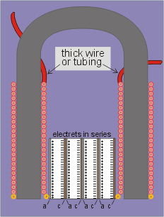 Another possible purpose for the horseshoe configuration, especially if the plastic blocks are indeed ELECTRETS might be to reduce the impedance of the wiring coiled around the horseshoe legs, which would of course improve the current output. Another possible purpose for the horseshoe configuration, especially if the plastic blocks are indeed ELECTRETS might be to reduce the impedance of the wiring coiled around the horseshoe legs, which would of course improve the current output.
Yet another possible reaction might be to double the oscillating frequency of the rectifier section of the circuit, particularly as there can be seen on some of the photographs of the Testatika machines a coil (or two coils) of different coloured wire around the horseshoe legs at the very bottom of the coilings of red wire, and these coilings would be connected to the outer plates of the plastic-blocks / electret setup for just such a mechanism (using the DC voltage from the electret) to operate (see fig.1 and the circuits below).
The thick wiring seen around the horseshoe, and at other places in the circuit is normal for high-voltage high-frequency circuits, whereby the electric current moves on the outer surface of the wire rather inside it. This 'skin effect' is counteracted by the use of multi-strand "Litz" wire or by using thick tubing (of 1/8" or 3mm dia).
Suitable parallels to Methernitha’s electronic principles, as can be seen from the circuit layouts included below, belong to a by-gone era of experimental radio electronics.
|
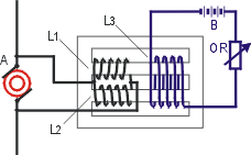 One of the techniques used in the early days of radio was a magnetic amplifier, to reduce the impedance of the coil-windings, to thereby increase the CURRENT in the circuit. The two coils L1 and L2 are wound in PARALLEL over the iron core and shunted across an oscillating current A. Coil L3 is connected to a DC source and regulated by resistance OR. The increase in current, using fairly simple circuitry, was 400%. ("Radio Telephony" Alfred N. Goldsmith (1918) p195-7; and see "Magnetic-Amplifier Circuits" William A Geyger (1954) p82) One of the techniques used in the early days of radio was a magnetic amplifier, to reduce the impedance of the coil-windings, to thereby increase the CURRENT in the circuit. The two coils L1 and L2 are wound in PARALLEL over the iron core and shunted across an oscillating current A. Coil L3 is connected to a DC source and regulated by resistance OR. The increase in current, using fairly simple circuitry, was 400%. ("Radio Telephony" Alfred N. Goldsmith (1918) p195-7; and see "Magnetic-Amplifier Circuits" William A Geyger (1954) p82)
|
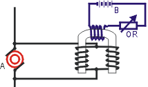 A very similar circuit was discovered which doubled or trebled the original frequency when a coil of DC current controlled the transformer core; to prevent the frequency increase but still control the original circuit a reactance coil is coupled to either the primary or the secondary. (From "Increasing Frequency by Static Transformers" by S.M. Powell in "The Electrical Review" Vol 73 Aug 29 (1913) p823) A very similar circuit was discovered which doubled or trebled the original frequency when a coil of DC current controlled the transformer core; to prevent the frequency increase but still control the original circuit a reactance coil is coupled to either the primary or the secondary. (From "Increasing Frequency by Static Transformers" by S.M. Powell in "The Electrical Review" Vol 73 Aug 29 (1913) p823)
|
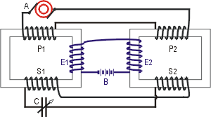 Various effects can be had from inserting a capacitor between two transformers. In this case, which resembles the Methernitha set-up, the coils are wound in such a way that the DC winding (E1 & E2) joins the two primary currents (P1 & P2) which lag 180° apart, and effectively doubles the frequency ("Radio Frequency Changers" by A.N. Goldsmith in "Proceedings of IRE" Vol 3 (1915) p74/5). Various effects can be had from inserting a capacitor between two transformers. In this case, which resembles the Methernitha set-up, the coils are wound in such a way that the DC winding (E1 & E2) joins the two primary currents (P1 & P2) which lag 180° apart, and effectively doubles the frequency ("Radio Frequency Changers" by A.N. Goldsmith in "Proceedings of IRE" Vol 3 (1915) p74/5).
|
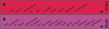 Volta's contact law Volta's contact law
When differing metals are brought into contact (dry) a difference of potentials exists between them.
|
|
The metals to the left exhibit positive potential when touched by any of the metals to the right in both the lists above (ie in a combination of copper/zinc - zinc would be positive, copper negative. Also, the pd between lead and gold would be greater than between iron and copper). For the voltage effect between two metals to be at its highest the surfaces of the metals must be smooth and clean (preferably cleaned with fine emery cloth) (also see "Electronic Influence Machines" by John Gray (1903) p191 and p201 about zinc / copper combinations and proportionally increasing voltages). |
Back to Home Page
|

