Please check at the bottom of this page for modifications to my van de graf generator design that may prove to work better than my original design featured here.
After many experiments and I trials I have built a simple high voltage generator. I am sure there are better combinations to get a high voltage source but I know this one will work and hope the following diagrams will aid you in building one if you wish.
You will need the following. A belt made of some nylon material I think mine was for use in curtain making about $6.00 a metre and more than enough for several home made belts .
Originally the trouble I found with belts is that I was unable to get them to glue and then to stand up to the strength required of the bond when under tension.
Nylon curtain material and a good contact adhesive will do the job here .I used one sold as K and S bond and costing about 3- 4 dollars a tube.
I used two stainless steel bowls up ended against one another and one drilled out in the center to allow the PVC tube to be attached to bowls and then stood up.on the support. I then purchased a simple rubberised wheel and placed it on a threaded 3/8" shaft along with three flat glued three circular disks of persplex to make a small drive pulley. (two larger than the center one)
I mounted this bottom pulley on the same shaft as the larger rubber wheel and mounted this into 3/8" bearing at each end of the driving shaft.
The bearings were mounted into patio metal angle supports any hard ware shop should be able to supply these about $1.80 each you will need four. If you can get some overside washers that will fit around your bearing this will make mounting the bearing on the end supports much easier and you can do the following..
Drill three bolt holes in these washers and into the same postion on the the patio angle metal ,the same for each of the four of the bearing supports.and then bolt into position. Put some contact glue around outside of bearings and inside the washers to help hold it together. You may also be able to to get a washer placed and secured on top of bearing to hold in place.
Use three/eights inch metal nuts to secure all threaded rod. One advantage in using threaded rod is that you measure needed not be critical in measure especially in nylon belt construction. Your belt side will be detirmed by the length you wish device to be and the width determined on the pulley sizes you can obtain.
I had trouble fiinding a proper upper pulley so I shaped a piece of wood on my lathe to resemble a wooden barrel in shape and mounted on a 3/8" metal shaft and into bearings as above.
This means you don't need special collectors at top to pick up high voltage as the voltage will pass through the wood and be able to be collected from the metal end supports. A wire lead is taken from here and into the dome at the top.
A piece of aluminium is close promity to the bottom of nylon belt helps in HV production. p>
Please note these supports need to insulated on and from the two upright threaded supports a piece of plastic cutting board is ideal.as shown in diagram
Also note keep the patio metal bearing support as far away as possible from your threaded supports that holds the upper part of the assembly.as high voltage jump over can occur as did my first try.
The nylon belt is simply made by cutting the size you desire and joining together with glue and then mounting onto the drive and pulley rollers as illustrated in diagrams.
Please note you may have to get the thread rod slighly machined to fit each end of it into bearing races.
The unit is driven is driven by an old electric sewing machine motor and rubber belt and does the job well
The best spark I have got is about 1/4" of inch. If you build one or have some tips let me know Geoff
Nylon roller with a rubber tire over it with a nylon roller at the top >will give you 25-30cm sparks on a hot dry day.... The belt is best made from two-ply 'rubber chair webbing'... splice one end over the other end for a perfect fault free joint. You can make any width and lenght belt 1mm-50mm x ? mm long. Use 'Contact Cement' as your flexible jointing glue... Have fun ... they are good fun to play with... my children love to play with my 300-400kv device. They have learned a great deal from it...
ROLLERS >Nylon 66 is used on the bottom roller, an a Risograph photocopier paper feed tyre is cemented over the nylon to give about a
50mm dia roller. The top roller is a 40-45mm dia roller cut out of a food grade nylon chopping board.
You will need to cut two pieces out of the chopping board and glue them together to get the roller wide enough for the belt to stay on while running. You will need a lathe or a power drill to carve out bearing slots in the nylon. Its a lot of fun making them.
The two dissimilar nylons will give you the potential difference needed to cause a voltage potential to develop. If you use the chopping board nylon at the top and the nylon 66 at the bottom you >will develop negative potentials on the condenser sphere.
Conversely swapping these rollers from top to bottom will give you a positive voltage on the condenser. Negative voltage is beneficial to your health to a small degree. Allowing yourself to come into contact with the sparks at 3 x 7 min intervals spaced by 30min rest periods will kill most parasites/worms/allergies in you body, and I've heard it will even treat some snake bites and detox the poison ??? See Bare/Rife frequency generator for more details.
2 ply rubber webbing:
| 50mm cut off |
=================== ==================================
-------Belt------------end 'A'---------------------------- ----------------Belt------end 'B'------------------------
=================================== ====================
| 50mm cut off |
*******************
> >New Belt spliced together:
=============||================================
-----------------------||=================== ||------------------------ Belt
=================================||=============
| 50 mm splice |
***********************
The Vandegraff device itself holds people spell bound when you show them some simple experiments.
Enjoy.
G.D.&C.M.Mutch [ New-Age Pioneer ]
Rockhampton. | Alternative : Energy,
Queensland. | Health, Wealth ,Personal ||
I Great/ s@uthern/ land/ * Australia. | & Social Values Today. II
Another helpful tip:
To get the real benefit of the bowls ability to collect a high voltage charge remember that the electric field inside of a hollow sphere is zero. If you place the upper roller and collector INSIDE of the sphere at the top of the support tube then the belt can carry (by mechanical motion) the charge inside the bowls. The charge will be collected (by a mesh) and then conducted (by a wire) to the inside surface of the bowls (which are at zero volts). This charge will be conducted to the surface of the bowls and will increase until conducted away by some form of leakage(like humidity) or in a spark. With the belt, collector and wire OUTSIDE of the bowls any additional charge is repelled away as soon as the voltage on the bowls is equal to that of the belts, which is indicated by the short spark discharges. If you rearrange your materials you should be able to achieve about 4 to 10 times the potential on the belt when the humidity is low. Clark Boyd
Modifications
Parts needed for this new design and are mostly the same as for the above design.
Drive motor
Belt
One small pulley mine was made up of circles cut out of persplex then glued and bolted together with nuts on the threaded shaft.
I large rubber wheel as in previous design but now mounted inside the plastic storm water pipe.
One screwed end cap
two joiners with a threaded end
A length of plastic storm water pipe to fit same.
and parts as shown in photographs.
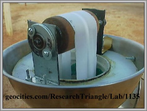
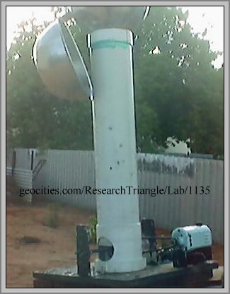
As can be seen from photographs I have now placed the top wooden roller inside the bowls as suggested by the above correspondent.
Some of the construction is as follow but by looking at photographs should give you a better idea of how to put it together.
A small cylinder about 1" is cut from a section of the second joiner and placed just under where the metal bowl is to sit upon.
One metal bowl having the bottom cut out, to allow it to fit over the storm water pipe is then placed upon upon the plastic support and then held in place by placing the remaining portion of the joiner on top of bowl to hold it in place.
The metal support angles are then placed on the plastic mounting board and fixed into place with small nuts and bolts.
The plastic mounting board is then placed around the top joiner inside the lower bowl.
The wooden roller is then placed between the two patio steel angles with a bearing races as shown on both steel supports in the photographs.
The roller axle is made of threaded metal shaft with each end machined just enough to fit in the bearing races at both ends.
The angle supports are mounted on a piece of plastic cutting board about 1/2"inch thick suitably cut to fit into the bowl and with a close fitting central hole to fit over the plastic joiner.
There is also a piece of brass shim from one metal support to the metal bowl to complete the electrical pathway.
I have noticed that a collector is not needed if the wooden top roller is mounted as in my design but a metal collector may also be an improvement.
A nylon belt is then made as described in a previous section of earlier design and is left to rotate inside the tube around both rollers.
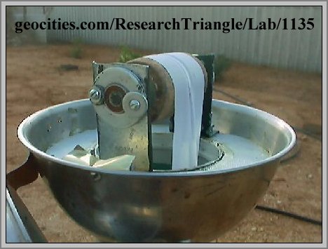
Another view of the same bowl and roller combination.
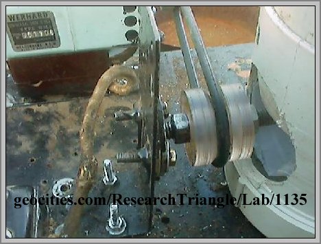
View of the bottom drive assembly similar to the first design but with belt and the large rubber wheel mounted inside the storm water pipe.
If you look at the bottom you will see a screw cap.
This is mounted to the board with three screws.
Next a threaded joiner is drilled out to allow the shaft of the bottom roller assembly to fit through to the other side..
I was unable to make a hole big enough to fit the large rubber wheel through but was able to fit it in position before putting the length of storm water pipe in place.
Related Webpages
Making a Wimshurst electrostatic machine
Making a Van de graaf electrostatic machine
The swiss Ml or testakica free energy machine that could use electrostatic principles
Making a capacitor with water and glass
making a high voltage capacitor simply
The Lorente electro static machine simple and excellent
using high voltage and a radio active element for free power.

Geoff Egel 18 Sturt Street, Loxton ,5333, South Australia ,Australia


